How We Manufacture M10 Bifacial Mono-PERC Solar Cells at Websol Energy System Ltd.
Websol Branding
on
February 10, 2026
How We Manufacture M10 Bifacial Mono-PERC Solar Cells at Websol Energy System Ltd.
People often ask us: “What actually happens inside a solar cell manufacturing facility?” It’s a fair question. The finished product – a thin, dark silicon wafer – doesn’t reveal the incredible precision and sophistication required to create it. Today, I want to take you on a detailed journey through our manufacturing process at Websol Energy System Ltd., showing you exactly how we transform raw silicon wafers into high-efficiency M10 bifacial mono-PERC solar cells.
This isn’t some generic overview copied from textbooks. This is our actual process, refined through years of experience, investments in state-of-the-art equipment, and continuous improvement driven by feedback from thousands of installations across India. Let’s walk through it step by step.
Starting Point: Incoming Wafer Inspection and Sorting
Our manufacturing process begins when monocrystalline silicon wafers arrive at our facility. These M10 wafers measure 182mm x 182mm and are sliced from large monocrystalline silicon ingots. Even though we procure these wafers from qualified suppliers, we never assume quality – every batch undergoes rigorous incoming inspection.
Our quality team visually inspects wafers for obvious defects like chips, cracks, or contamination. Then automated optical inspection systems scan each wafer, checking thickness uniformity, edge quality, and surface defects. Wafers failing these initial checks are rejected immediately. We maintain a rejection rate of less than 0.5% at this stage, thanks to our stringent supplier qualification process, but that scrutiny is non-negotiable.
Wafers that pass inspection are sorted by thickness and resistivity. Even small variations in these parameters affect cell performance, so we group wafers with similar characteristics together. This sorting ensures uniformity within each production batch, critical for consistent cell output and easier module assembly downstream.
The wafers are then cleaned in an ultrasonic bath using deionized water and specialized cleaning solutions. This removes any particulate contamination, organic residues, or metallic impurities from the wafer surface. Clean surfaces are essential for the chemical processes that follow.
Surface Texturing: Creating the Light-Trapping Structure
The first major process step is surface texturing. Polished silicon surfaces are highly reflective – they bounce away 30-35% of incident light, which is obviously wasteful in a solar cell. We need to capture as much light as possible, and texturing solves this problem elegantly.
We use an alkaline etching process where wafers are immersed in a hot potassium hydroxide (KOH) solution. The alkaline solution preferentially etches certain crystal planes of the monocrystalline silicon, creating millions of tiny pyramids across the wafer surface. Each pyramid is typically 5-10 micrometers tall.
These pyramids serve two purposes. First, they trap incoming light through multiple internal reflections, ensuring most photons are absorbed rather than reflected away. This reduces total reflectivity to under 5%. Second, the angled surfaces help light enter the silicon at various angles, improving absorption across different wavelengths.
After texturing, wafers undergo multiple rinse cycles in deionized water to remove all KOH residue. Any remaining alkali would interfere with subsequent process steps. The rinse water’s pH and conductivity are continuously monitored to ensure complete cleaning.
Diffusion: Creating the p-n Junction
The heart of any solar cell is the p-n junction – the boundary between p-type and n-type silicon where the photovoltaic effect actually occurs. Our M10 wafers start as p-type silicon (doped with boron during ingot growth). We need to create a thin n-type layer on the surface through a process called phosphorus diffusion.
Wafers are loaded into high-temperature diffusion furnaces (typically 800-900°C) in a controlled atmosphere. Phosphorus oxychloride (POCl3) vapor is introduced into the furnace. At high temperature, phosphorus atoms diffuse into the silicon surface, creating an n-type layer typically 0.3-0.5 micrometers deep.
The diffusion profile – how deeply and uniformly phosphorus penetrates – critically affects cell performance. Too shallow, and series resistance increases. Too deep, and carrier recombination increases. Our process engineers have optimized this to achieve ideal junction depth and surface concentration through precise temperature control and diffusion duration.
After diffusion, a phospho-silicate glass (PSG) layer forms on the surface as a byproduct. This must be removed through etching in hydrofluoric acid (HF) solution. The PSG removal process is carefully timed to remove only the glass layer without damaging the underlying diffused silicon.
Edge Isolation: Preventing Shunting
During diffusion, phosphorus wraps around to the rear surface of the wafer, creating a connection between front and rear that would short-circuit the cell. We need to remove this edge diffusion through an edge isolation process.
We use laser ablation for edge isolation. A precisely controlled laser beam traces the wafer perimeter, removing the diffused n-type layer from the edges and rear surface. This creates electrical isolation between front and rear surfaces while maintaining the p-n junction on the front.
The laser parameters – power, pulse duration, scanning speed – are carefully optimized. Too much energy damages the silicon or creates microcracks. Too little fails to completely remove the diffusion. Our laser systems are computer-controlled and regularly calibrated to maintain precision.
After laser ablation, wafers undergo another cleaning cycle to remove debris generated during the laser process. This cleaning is crucial because any conductive particles left on the surface could create shunt paths that reduce cell efficiency.
PERC Layer Application: The Key Differentiator
Now we reach the PERC (Passivated Emitter and Rear Cell) process steps that differentiate our cells from standard monocrystalline products. This is where we add the rear-side passivation that gives PERC cells their superior efficiency.
First, we apply a thin dielectric layer – typically aluminum oxide (Al2O3) – to the rear surface using atomic layer deposition (ALD) or plasma-enhanced chemical vapor deposition (PECVD). This layer is incredibly thin, just 5-20 nanometers, but its impact is profound.
The aluminum oxide layer serves two crucial functions. It creates a negative fixed charge that repels electrons away from the rear surface, reducing recombination losses. It also passivates defects on the silicon surface that would otherwise act as recombination centers. Together, these effects significantly improve cell efficiency.
On top of the aluminum oxide, we deposit a silicon nitride (SiNx) layer, typically 70-100 nanometers thick. This serves as a capping layer that protects the aluminum oxide and provides additional optical benefits.
The deposition parameters – temperature, gas flow rates, chamber pressure, deposition time – are tightly controlled. Our PECVD systems are equipped with real-time monitoring to ensure layer thickness uniformity across each wafer and consistency across batches. Even a 10% variation in thickness can measurably affect cell performance.
Laser Contact Opening: Creating Rear-Side Access Points
For bifacial cells, we can’t just apply a solid aluminum layer on the rear as you would with monofacial cells – that would block light from entering the rear. Instead, we create a pattern of small contact points while leaving most of the rear surface open for light transmission.
Using laser ablation, we create thousands of tiny openings (typically 50-100 micrometers diameter) through the passivation layers at precise locations. These openings expose the underlying silicon, allowing electrical contact while maintaining passivation over most of the rear surface.
The laser contact opening process requires incredible precision. The laser must completely remove the passivation layers without damaging the silicon underneath. Our laser systems use rapid pulse control and real-time feedback to achieve this. The pattern density and geometry are optimized to balance electrical performance against bifacial light transmission.
Anti-Reflective Coating: Maximizing Light Absorption
While the textured surface already reduces reflection significantly, we further minimize losses by applying an anti-reflective coating (ARC) to the front surface. We use a silicon nitride layer deposited through PECVD, similar to the rear capping layer but with different thickness and composition.
The ARC thickness is precisely tuned (typically 70-80 nanometers) to minimize reflection at wavelengths where silicon absorption is strongest. The blue color you see on most solar cells is actually the result of this anti-reflective coating – it’s designed to reflect blue/violet light slightly while absorbing most of the solar spectrum.
Our PECVD systems can deposit ARC on entire batches of wafers simultaneously, ensuring excellent uniformity. After deposition, wafers undergo optical inspection to verify coating thickness and uniformity. Wafers with coating defects are identified and either reprocessed or rejected.
Metallization: Creating the Electrical Contacts
Now we need to add metal contacts that collect the electrical current generated by the cell. This metallization process is critical because the contacts must collect current efficiently while minimizing shadowing and resistance losses.
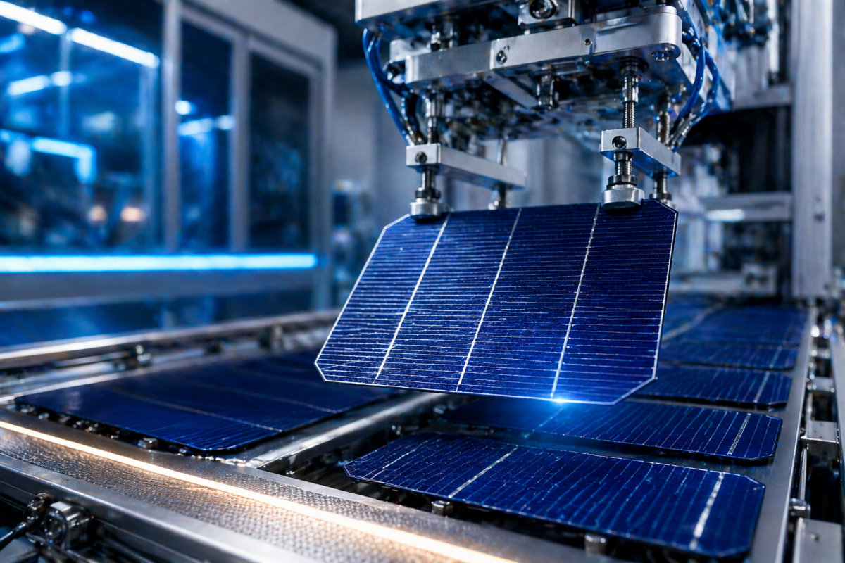
For the front surface, we use screen printing to apply a silver paste in a fine finger pattern. Modern M10 cells typically use a multi-busbar (MBB) design with 9-12 busbars and fine fingers connecting to them. The paste is carefully formulated to achieve good adhesion and low contact resistance.
Screen printing requires precision. The screens must be perfectly aligned, the paste viscosity must be optimal, and the printing pressure and speed must be controlled. Our printing equipment uses computer vision systems for automatic alignment and quality verification after each print.
For the rear surface of bifacial cells, we print an aluminum paste at the laser-opened contact points and a silver paste for the busbar pattern. The open pattern allows light transmission while the aluminum creates good electrical contact to the p-type silicon base.
After printing, wafers are dried in infrared ovens to remove solvents from the paste. This drying must be gentle to avoid paste cracking or spreading that would affect performance.
Firing: Forming the Electrical Contacts
The printed metal pastes need to be fired at high temperature to form good electrical contact with the silicon. Wafers pass through a multi-zone furnace belt at carefully controlled speeds, experiencing a precise temperature profile.
The firing process is arguably the most critical step in cell manufacturing. During firing, the silver paste penetrates through the anti-reflective coating to make contact with the silicon. The aluminum paste creates a back surface field (BSF) that enhances rear-side performance. The temperature profile must be optimized to achieve good contact formation without damaging the silicon or causing metal diffusion issues.
Our firing furnaces have 10+ temperature zones, each independently controlled. The peak temperature (typically 700-850°C), ramp rates, and dwell times are optimized through extensive testing. Process engineers continuously monitor furnace performance and adjust parameters based on output cell characteristics.
Testing and Sorting: Quality Verification
After firing, every single cell undergoes comprehensive electrical testing. This is non-negotiable – we test 100% of production, not just random samples.
Each cell passes through a flash tester that simulates sunlight and measures the cell’s I-V (current-voltage) curve. This provides crucial parameters: short-circuit current (Isc), open-circuit voltage (Voc), maximum power point (Pmp), fill factor (FF), and overall efficiency. The test takes just seconds per cell but provides complete performance characterization.
Cells are sorted into different efficiency bins – typically in 0.1-0.2% increments. This sorting is crucial for module manufacturing because you can’t mix cells with significantly different outputs in the same module without creating electrical mismatches that reduce performance.
Electroluminescence (EL) imaging is performed on sample cells from each batch and any cells that flagged during flash testing. EL imaging reveals defects invisible to the naked eye – microcracks, broken fingers, junction defects, shunt issues. Cells with such defects are rejected.
We also perform statistical process control (SPC) analysis on test data. This identifies trends or variations in the manufacturing process before they become serious problems. If we see cell efficiency trending downward, even slightly, we investigate immediately to identify and correct the root cause.
Final Inspection and Packaging
Cells that pass electrical testing undergo final visual inspection. Automated optical inspection systems scan for cosmetic defects, contamination, or damage that might affect long-term reliability even if electrical parameters are within specification.
Approved cells are carefully packaged for shipment to module manufacturing facilities (either our own or our customers’). Packaging must protect these delicate silicon wafers from physical damage during handling and transportation. We use specialized trays with individual cell compartments and anti-static protection.
Each package is labeled with complete traceability information – production batch, date, efficiency bin, quantity. This traceability is crucial for quality management and allows tracking of any issues back to specific manufacturing batches.
Quality Management: The Foundation of Reliability
Throughout this entire process, quality management is paramount. As a leading Bifacial Mono-PERC Solar Cell Manufacturer in India, we maintain comprehensive quality systems aligned with international standards.
Every process step has defined specifications and control limits. In-process measurements are taken continuously, and Statistical Process Control charts track every critical parameter. When any parameter approaches control limits, corrective action is triggered before defects occur.
We conduct regular environmental stress testing on sample cells from production batches. This includes thermal cycling, humidity-freeze, damp heat, and UV exposure tests. These tests simulate years of field operation and verify long-term reliability.
Our quality team also conducts regular supplier audits for incoming materials and periodic equipment calibration to ensure measurement accuracy. The calibration records and test data are maintained for years, providing complete documentation of quality management efforts.
Continuous Improvement: Learning and Evolving
Manufacturing excellence isn’t achieved once and forgotten – it requires continuous improvement. We maintain detailed records of process parameters, quality metrics, and equipment performance. This data is analyzed to identify improvement opportunities.
Our R&D team collaborates closely with production engineers, testing new process variations on pilot lines before full-scale implementation. Recent improvements include optimized PERC layer deposition recipes that improved average cell efficiency by 0.15% and refined firing profiles that reduced contact resistance.
We also actively seek feedback from module manufacturers and end users. Field performance data from installations helps us understand how cells perform in real-world conditions and guides our testing and qualification procedures.
Our engineers participate in industry conferences, visit equipment suppliers, and collaborate with research institutions to stay current with advancing technology. The solar industry evolves rapidly, and maintaining leadership requires continuous learning and adaptation.
Environmental Responsibility in Manufacturing
We’re committed to environmentally responsible manufacturing. Our facility includes waste treatment systems that neutralize acids and alkalis before discharge. Process chemicals are recycled wherever possible, and hazardous waste is handled through certified disposal services.
Energy efficiency is a priority. We’ve installed LED lighting throughout the facility, optimized HVAC systems, and implemented energy management systems that identify waste. Ironically, some people don’t realize that manufacturing solar cells consumes energy, so minimizing that consumption improves the overall sustainability profile.
We’ve also invested in solar installation on our factory roof – currently 5 MW capacity that meets approximately 60% of our manufacturing energy needs during daylight hours. There’s something satisfying about manufacturing solar cells using solar-generated electricity.
The Human Element: Skilled Workforce
While our process involves sophisticated automation and equipment, skilled people remain essential. Our manufacturing engineers, technicians, quality inspectors, and operators receive extensive training and ongoing skill development.
New technicians undergo 3-4 weeks of classroom and on-the-job training before independently operating equipment. Engineers participate in advanced training programs covering process physics, equipment technology, and quality systems. This investment in human capital is crucial for maintaining manufacturing excellence.
The solar industry in India is creating thousands of skilled manufacturing jobs, contributing to economic development while supporting the energy transition. At Websol Energy System Ltd., we’re proud to be part of this job creation while advancing India’s self-reliance in critical clean energy technology.
Looking Forward: Next-Generation Manufacturing
While our current PERC manufacturing process is highly optimized and delivers excellent results, we’re already preparing for the next generation. We’re piloting TOPCon (Tunnel Oxide Passivated Contact) cell production, which will push efficiencies beyond 24% while building on our PERC manufacturing expertise.
We’re also exploring automation improvements using AI and machine learning for quality inspection, predictive maintenance, and process optimization. The future of solar cell manufacturing will involve even greater precision and intelligence, and we’re positioning ourselves at that frontier.
As a solar cell manufacturer in India, we’re committed to manufacturing excellence that makes Indian solar cells competitive with the best in the world. The process I’ve described today – from incoming wafers to finished cells – represents years of refinement and investment. It’s this attention to detail, commitment to quality, and continuous improvement that enables us to deliver the high-efficiency, reliable M10 bifacial mono-PERC cells powering India’s solar revolution.