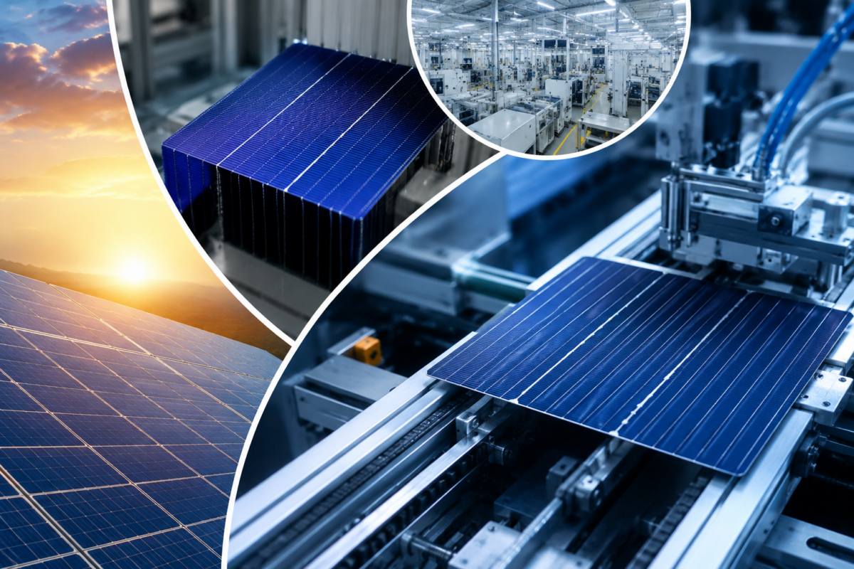
The Complete Guide to Solar Cell Manufacturers in India

The Complete Guide to Solar Cell Manufacturers in India

India’s solar manufacturing sector has undergone a structural transformation over the past five years. What was once a landscape dominated by module assemblers reliant on imported cells has steadily evolved into a more vertically integrated ecosystem. Today, Indian solar cell manufacturers supply not just domestic EPC companies and developers but are increasingly attracting interest from procurement teams across Southeast Asia, the Middle East, and Africa.

For EPC contractors, project developers, and institutional buyers, selecting the right upstream partner — a manufacturer with the right technology stack, capacity, and quality controls — has become as important as choosing the right land parcel or offtake agreement. This guide breaks down what India’s solar cell manufacturing sector looks like today, what to evaluate when shortlisting vendors, and where the market is headed.

The Current Landscape of Solar Cell Manufacturing in India

India’s installed solar manufacturing capacity has expanded significantly under the Production Linked Incentive (PLI) scheme and the Basic Customs Duty (BCD) structure that came into effect in 2022. These policy instruments were designed to shift procurement away from imported Chinese cells and modules toward domestically produced alternatives.

As of mid-2024, India’s solar cell manufacturing capacity stood at approximately 8–10 GW annually, with several manufacturers operating at multi-gigawatt scale. The majority of this capacity is concentrated in Gujarat, Rajasthan, Tamil Nadu, and West Bengal. The technology mix has also shifted — MonoPERC remains the dominant cell architecture, but N-type topologies including TOPCon are entering commercial production at several facilities.

Websol Energy System Ltd, headquartered in Falta, West Bengal, is one of India’s established photovoltaic cell manufacturers, with a focus on monocrystalline cell production and ongoing capacity expansion. The company’s manufacturing approach reflects the broader industry trend toward higher-efficiency architectures and tighter process controls.

Key Technology Architectures in Indian Solar Cell Manufacturing


MonoPERC

Passivated Emitter and Rear Cell (PERC) technology added a dielectric passivation layer to the rear of monocrystalline cells, recovering photons that would otherwise be lost as heat. MonoPERC cells now routinely achieve efficiencies between 22% and 22.8% at commercial scale, making them the workhorse of utility-scale procurement in India today.

N-Type Technologies

N-type silicon substrates inherently have lower boron-oxygen defect densities than P-type, which translates into lower light-induced degradation (LID) and better performance in high-temperature conditions. TOPCon (Tunnel Oxide Passivated Contact) and HJT (Heterojunction Technology) are the two primary N-type architectures scaling commercially. TOPCon cells are approaching 24%+ efficiencies in production, while HJT cells offer superior temperature coefficients but require more capital-intensive tooling.

M10 Wafer Format

The industry-wide shift to larger wafer formats — particularly M10 (182mm x 182mm) — has been driven by the efficiency and watt-per-cell gains that come from increased cell area. M10 has emerged as a near-standard format for new module production lines globally, and Indian manufacturers that have retooled for M10 are better positioned for supply chain alignment with downstream module buyers.

What to Evaluate When Selecting a Solar Cell Manufacturer

Efficiency Binning and Consistency

Raw peak efficiency numbers are less meaningful than the distribution of your actual supply. A manufacturer delivering cells with a tight efficiency distribution — say, within a 0.2% band around the nominal value — enables more consistent module output and reduces sorting losses for module assemblers.

Process Certifications and Quality Systems

ISO 9001 quality management systems are baseline. Beyond that, manufacturers supplying to serious project developers should be able to demonstrate IEC-compliant testing protocols, third-party audits, and traceability systems that satisfy lenders and EPCs running bankability assessments.

Capacity Utilization and Lead Times

A manufacturer operating at 95% capacity utilization with no confirmed expansion plan is a supply risk. Understanding where a potential supplier sits in their utilization cycle, and how they manage allocation during peak demand, is critical for project scheduling.

Technology Roadmap

India’s domestic solar manufacturing is transitioning from P-type to N-type architectures. Manufacturers that have articulated and funded a technology transition plan — toward TOPCon or N-type MonoPERC — represent more durable supply relationships than those locked into depreciating P-type lines.

The Role of Made-in-India Solar Cells in Project Financing

Since the implementation of the Approved List of Models and Manufacturers (ALMM) in India, domestically produced solar cells and modules have taken on regulatory significance beyond just price competitiveness. Projects seeking SECI, NTPC, or state DISCOM offtake agreements are generally required to source from ALMM-listed manufacturers. This has created a structured demand channel for domestic cell producers that didn’t exist three years ago.

For international project developers operating in India, understanding ALMM compliance is not optional — it is a procurement requirement. Selecting a manufacturer already on the ALMM list, or one actively pursuing listing, eliminates a potential financing bottleneck.

Geographic Concentration and Supply Chain Resilience

India’s solar cell manufacturing ecosystem is not uniformly distributed. West Bengal, for instance, is home to several established manufacturers including Websol, which benefits from proximity to Kolkata’s logistics infrastructure and access to skilled technical labor developed over decades of industrial electronics manufacturing in the region.

Buyers sourcing from multiple geographically dispersed Indian manufacturers reduce concentration risk — particularly relevant in a market where unexpected policy changes, raw material disruptions (polysilicon, silver paste), or logistics constraints can affect a single-source supply strategy.

Final Words

India’s solar cell manufacturing sector is no longer a secondary option for buyers trying to avoid Chinese supply chain dependencies. It is an increasingly mature, technically capable, and policy-supported ecosystem. For EPCs and project developers building procurement strategies for the next three to five years, engaging directly with Indian photovoltaic cell manufacturers — understanding their technology roadmaps, quality systems, and capacity plans — is a foundational step in building supply chain resilience.

The next generation of large-scale solar projects in India and beyond will increasingly be built on cells manufactured domestically. The question is not whether to engage with Indian solar cell manufacturers, but which ones are building the capabilities to support the scale and quality demands of tomorrow’s projects.

Frequently Asked Questions


  1. What does a solar cell manufacturer in India do?

A solar cell manufacturer in India produces photovoltaic cells by processing silicon wafers through diffusion, metallization, and passivation processes. These cells are later assembled into solar modules used in residential, commercial, and utility-scale solar power installations.

  1. How many solar cell manufacturers are there in India?

India has a limited number of integrated solar cell manufacturers. While many companies assemble solar modules, only a smaller group operates large-scale photovoltaic cell manufacturing facilities.

  1. What technologies are used in solar cell manufacturing in India?

Most Indian manufacturers produce MonoPERC solar cells, while several companies are transitioning to N-type technologies such as TOPCon and HJT to improve efficiency and energy yield.

  1. Why are domestically manufactured solar cells important for India?

Domestic solar manufacturing strengthens energy security, reduces reliance on imports, and supports India’s renewable energy targets while improving supply chain resilience.

  1. What certifications should solar cell manufacturers have?

Solar cell manufacturers should comply with international quality and safety standards such as IEC certifications, ISO quality systems, and ALMM compliance for government-approved solar projects in India.

  1. What is a photovoltaic solar cell?

A photovoltaic solar cell is a semiconductor device that converts sunlight into electricity through the photovoltaic effect. These cells are the fundamental building blocks used to produce solar modules and panels.

  1. What is the difference between solar cell manufacturing and solar module assembly?

Solar cell manufacturing involves producing photovoltaic cells from silicon wafers, while solar module assembly connects multiple cells together, encapsulates them, and creates finished solar panels.

MonoPERC vs N-Type vs M10: Choosing the Right Solar Cell Technology

MonoPERC vs N-Type vs M10: Choosing the Right Solar Cell Technology for Your Project

Solar cell technology has never moved faster — or diverged more significantly across commercial offerings. Three years ago, MonoPERC was the unambiguous choice for utility-scale procurement. Today, procurement teams are fielding offers for TOPCon, HJT, and bifacial-capable N-type cells alongside conventional MonoPERC, while simultaneously navigating a shift in wafer formats driven by the industry-wide adoption of M10 (182mm) and G12 (210mm) substrates.

The result is a decision matrix that’s considerably more complex than it was in 2021. This article unpacks each major technology category — MonoPERC, N-type, and M10 as a format consideration — and maps them against the project types and procurement contexts where each performs best.

MonoPERC: The Commercial Workhorse

MonoPERC cells combine monocrystalline silicon’s superior carrier mobility with rear-surface passivation that reduces recombination losses. The practical result is efficiency levels that regularly reach 22–22.8% in volume production, with temperature coefficients around -0.35%/°C and well-understood degradation profiles.

For project developers, MonoPERC’s primary advantage is bankability. It has the longest commercial track record of any current mainstream architecture. Module manufacturers, inverter companies, and performance modelers all have extensive empirical data on MonoPERC behavior across diverse climatic conditions. This reduces the due diligence burden for lenders and technical advisors on large-scale projects.

MonoPERC also benefits from a mature supply chain. Wafer producers, silver paste suppliers, anti-reflection coating vendors, and testing labs have all optimized around this architecture. The result is competitive pricing and, crucially, pricing predictability — something that matters significantly when modeling project IRRs over 25-year periods.

Where MonoPERC Makes Sense

MonoPERC remains the right call for projects where technology risk appetite is low, where lender requirements favor established architectures, and where upfront cost minimization outweighs marginal efficiency gains. Community solar, rooftop commercial, and utility projects in financing-constrained markets are the natural home of MonoPERC procurement through mid-decade.

N-Type Technologies: TOPCon and HJT

N-type silicon cells use phosphorus-doped substrates instead of the boron-doped P-type silicon that underlies MonoPERC. The physics are important: N-type substrates have inherently lower boron-oxygen recombination defects, which means less light-induced degradation — a meaningful performance advantage over the first two years of operation.

TOPCon

Tunnel Oxide Passivated Contact (TOPCon) adds a thin tunneling oxide and doped polysilicon layer to the rear of the cell, providing excellent passivation with efficiency potential reaching 24.5%+ at lab scale and 23.5–24% in volume production at leading manufacturers. The manufacturing process is compatible with existing PERC production lines, which has accelerated its adoption — several Indian manufacturers are currently commissioning or planning TOPCon conversions.

The performance advantage over MonoPERC is most pronounced at elevated temperatures and in diffuse light conditions, making N-type TOPCon particularly relevant for humid coastal climates and locations with high average irradiance temperatures. Annual energy yield improvements of 3–5% over equivalent-wattage MonoPERC modules are commonly cited in independent assessments.

HJT

Heterojunction Technology cells stack amorphous silicon layers on both sides of a crystalline substrate, delivering the industry’s best temperature coefficients (around -0.24%/°C) and bifaciality factors above 90%. HJT cells can exceed 25% efficiency at production scale. The constraint is manufacturing cost: HJT requires lower-temperature processing equipment incompatible with standard PERC lines, and silver consumption per cell remains higher than TOPCon.

HJT is currently best suited to premium applications where watt-density, bifacial gain, and long-term degradation rates carry higher weighting in the investment case — rooftop systems with premium feed-in tariffs, building-integrated PV, and select utility projects with high land constraints.

M10 Wafer Format: Why Cell Dimensions Matter

The transition from M2 (156.75mm) and M4 (161.75mm) wafers to M10 (182mm) and G12 (210mm) formats reflects a fundamental economic logic: more silicon area per cell means more watts per cell, which reduces the number of cells per module, cuts interconnection labor, and improves watts-per-module without necessarily improving cell efficiency.

M10 has emerged as the dominant format for new manufacturing lines globally. Manufacturers like Websol that have oriented their high-efficiency solar cell production toward M10 are better aligned with the module bill-of-materials requirements of downstream buyers. G12, while capable of even higher module outputs, introduces mechanical handling and balance-of-system challenges that have limited its penetration outside of specific utility-scale applications.

Format Compatibility with Module Production

For EPC companies that also operate module production lines or have close supplier relationships with module manufacturers, cell format compatibility is not academic. Introducing cells of a different format requires changes to tabbing equipment, encapsulant cutting, and framing. Understanding which formats your module partner is equipped to process should be an early step in cell procurement planning.

Making the Decision: A Framework

No single technology is universally optimal. The right choice depends on project duration, financing structure, climate, land availability, and the buyer’s appetite for technology risk. A useful framework:

For near-term projects (commissioning within 18 months) with conventional financing: MonoPERC remains low-risk and cost-competitive. For projects with a 24–36 month development runway and where annual energy yield will drive valuation: TOPCon warrants serious evaluation. For premium applications where efficiency density and bifacial performance carry premium pricing: HJT is worth the cost premium analysis. In all cases, M10 should be the default format consideration for new procurement.

Conclusion

The solar cell technology landscape in 2024 rewards informed procurement. The difference between a MonoPERC, TOPCon, and HJT selection is no longer just an equipment choice — it affects modeled energy yields, financing conversations, and long-term portfolio performance. Indian solar cell and module manufacturers are increasingly offering multiple technology options across these architectures, giving domestic and international buyers more flexibility than at any previous point in India’s manufacturing history.


Frequently Asked Questions


  1. What is the difference between MonoPERC and N-type solar cells?

MonoPERC solar cells are based on P-type silicon and use rear-surface passivation to improve efficiency and reduce recombination losses. N-type solar cells use phosphorus-doped silicon, which reduces light-induced degradation and improves performance in high-temperature conditions. As a result, N-type technologies like TOPCon often deliver higher long-term energy yield.

  1. Why are N-type solar cells becoming more popular in large solar projects?

N-type solar cells are gaining popularity because they offer higher efficiency, lower degradation rates, and better performance under high temperatures and low-light conditions. Technologies such as TOPCon and HJT can deliver improved energy output over the lifespan of a solar project, making them attractive for utility-scale installations.

  1. What is the M10 wafer format in solar cell manufacturing?

The M10 wafer format refers to a larger silicon wafer size measuring 182mm × 182mm. Larger wafer sizes allow manufacturers to produce cells with greater surface area, which increases watt output per cell and helps create higher-power solar modules used in modern solar installations.

  1. Which solar cell technology is best for utility-scale solar projects?

MonoPERC remains widely used for utility-scale solar projects due to its proven reliability and mature supply chain. However, many developers are now evaluating N-type technologies such as TOPCon because they provide higher efficiency and improved long-term energy generation in large solar farms.

  1. How do EPC companies choose the right solar cell technology?

EPC companies evaluate several factors when selecting solar cell technology, including efficiency levels, degradation rates, project climate conditions, module compatibility, and overall cost per watt. The decision often depends on balancing upfront costs with long-term energy yield and project financing requirements.

  1. What is MonoPERC solar cell technology?

MonoPERC (Passivated Emitter and Rear Cell) is a solar cell technology that improves efficiency by adding a passivation layer on the rear side of a monocrystalline silicon cell. This layer reflects unused photons back into the cell, allowing it to generate more electricity from the same sunlight.

  1. What is the difference between M10 and G12 solar wafers?

M10 and G12 are large-format silicon wafer sizes used in solar cell manufacturing. M10 wafers measure 182mm × 182mm, while G12 wafers measure 210mm × 210mm. Larger wafer sizes allow solar manufacturers to produce higher-wattage modules with fewer cells, improving manufacturing efficiency and reducing system costs.

M10 Solar Cells: Efficiency, Output & Manufacturing Advantages

M10 Solar Cells: Efficiency, Output & Manufacturing Advantages

The solar industry’s shift to larger wafer formats represents one of the most significant structural changes in photovoltaic manufacturing over the past decade. The M10 wafer format — measuring 182mm × 182mm — has emerged as the dominant cell size in global solar manufacturing and is now the baseline specification for most new module production lines. For procurement teams, EPCs, and module manufacturers evaluating cell supply, understanding why M10 has achieved this position, and what it means for module performance and manufacturing economics, is fundamental.

The Wafer Format Evolution: Context for M10

Solar cell wafer formats were effectively standardized around M2 (156.75mm) and M4 (161.75mm) for much of the 2010s. The logic of staying with smaller formats was conservative: existing tooling, transport packaging, and module bill-of-materials were all optimized around them. The disruption began when Longi and several other major manufacturers introduced M6 (166mm) and subsequently M10 (182mm) as production formats, demonstrating that the watt-per-cell gains from larger area more than offset the retooling costs.

G12 (210mm) emerged as an alternative large-format choice from a different manufacturing coalition, but M10 has consolidated its position as the de facto industry standard for most module types — particularly for the half-cell and multi-busbar (MBB) module designs that dominate current production.

Why M10 Delivers Efficiency and Output Advantages

Cell Area and Watts per Cell

The M10 cell area (approximately 332 cm²) is roughly 30% larger than a standard M2 cell. With the same conversion efficiency, this directly translates to 30% more watts per cell. In a 60-cell equivalent module configuration, this means significantly higher module wattage without requiring a proportional efficiency improvement. A 22% efficient M10 cell produces approximately 7.3W, compared to approximately 5.6W from a 22% M2 cell.

Half-Cell Architecture Compatibility

M10 cells are predominantly used in half-cell configurations, where each cell is cut in half along its long axis before interconnection. Half-cell modules operate at half the current of full-cell equivalents, reducing resistive losses in interconnection and improving shade tolerance. The M10 half-cell has become the standard building block of 400–500W+ module designs that now dominate utility procurement.

Multi-Busbar (MBB) Advantages

M10 cells are typically produced with 9 or 12 busbars (compared to 5–6 in older designs), increasing current collection efficiency and reducing silver paste consumption per watt. MBB technology also reduces the impact of micro-cracks on cell performance, as current paths are shorter and more redundant. This improves the mechanical durability of cells during module lamination and subsequent field operation.

Manufacturing Economics of M10 Production

The shift to M10 improved manufacturing economics through several mechanisms. Throughput per tool is higher with larger cells — a diffusion furnace processing M10 wafers produces more watts per production run than the same tool processing M2 wafers at the same efficiency. This dilutes equipment depreciation costs per watt produced.

Silver paste consumption per watt has also declined with M10, despite the larger cell area, due to the combination of MBB technology and optimized printing processes. Silver is the highest-cost cell input after the silicon wafer itself, so reducing silver per watt is a meaningful cost lever.

For Indian solar cell manufacturers that have invested in M10-capable production lines — including equipment capable of handling the larger wafer without yield loss from edge breakage or handling damage — the economics are materially better than equivalent older-format lines. Websol’s manufacturing capabilities include M10 cell production, positioning their cell supply for compatibility with current-generation module production lines used by their customers.

Supply Chain Alignment: Buying M10 Cells in India

The shift to M10 has created a supply chain realignment challenge for module manufacturers that upgraded to M10 module production lines but found domestic cell supply concentrated in older formats. As Indian cell producers retool for M10, this gap is narrowing — but buyers should verify that the format specification of cells they are procuring is genuinely M10 and compatible with their specific module production equipment.

Key cell format specifications to verify include the wafer size (182mm ± tolerance), corner cut dimensions (consistent with 166mm or M10 standard), and the busbar pitch (relevant for tabbing machine calibration). Discrepancies in any of these dimensions can cause yield losses in module production that are not apparent until production begins.

M10 and the Transition to N-Type

The M10 format is format-agnostic with respect to cell architecture — both P-type MonoPERC and N-type TOPCon cells are produced in M10. As the industry transitions toward N-type architectures, M10 remains the dominant format for TOPCon production. Buyers planning to transition their module production from MonoPERC to TOPCon cells can maintain M10 format consistency through this transition, simplifying the retooling requirements.

Conclusion

M10 solar cells represent the current optimization point in the trade-off between cell size, module design flexibility, manufacturing economics, and supply chain compatibility. For procurement teams sourcing high-efficiency solar cells in India, specifying M10 aligns with the dominant global format, ensures compatibility with current-generation module tooling, and accesses the better per-watt economics that larger cell formats enable. Indian manufacturers investing in M10 production are building capabilities aligned with where both domestic and export module manufacturing demand is concentrated.

Frequently Asked Questions

  1. What are M10 solar cells?

M10 solar cells are photovoltaic cells made using 182mm silicon wafers, allowing higher watt output and improved module efficiency.

  1. Why are M10 wafers used in solar manufacturing?

M10 wafers increase cell surface area, enabling manufacturers to produce higher power solar modules with fewer cells.

  1. What are the advantages of M10 solar cells?

Advantages include higher power output, improved manufacturing efficiency, and compatibility with modern module designs.

  1. Are M10 solar cells better than older formats?

Yes. Compared to smaller wafer formats, M10 cells enable higher watt modules and more efficient production processes.

  1. What module wattage can M10 cells produce?

Modules built with M10 cells commonly reach 400W–600W or higher depending on design.

  1. What is a solar wafer?

A solar wafer is a thin slice of crystalline silicon used as the base material for manufacturing photovoltaic cells.

  1. Why are larger solar wafers important?

Larger wafers allow manufacturers to produce higher watt modules while reducing manufacturing costs per watt.

How Bifacial Solar Cells Are Transforming Large-Scale Solar Projects

How Bifacial Solar Cells Are Transforming Large-Scale Solar Projects

Bifacial solar cells were a niche technology five years ago — interesting in concept, constrained in bankability, and limited in the project types where they made economic sense. That picture has changed substantially. By 2023, bifacial modules accounted for the majority of new utility-scale installations globally, and in India, their adoption has accelerated sharply as installation practices, financial models, and supply chains have matured around them.

Understanding how bifacial cells work, where they deliver genuine yield improvements, and what they require to perform as modeled is now a core competency for anyone involved in the design, procurement, or financing of large-scale solar projects.

The Physics of Bifacial Cell Design

A conventional monofacial cell converts sunlight striking its front surface into electricity. Rear-surface metallization and a reflective backing sheet prevent rear-surface photon capture. Bifacial cell architecture removes this constraint by using transparent rear materials — typically a passivated rear contact structure — that allow albedo light (light reflected from the ground or surrounding surfaces) to enter and generate additional current.

The bifaciality factor — typically expressed as a percentage — describes how effectively the rear surface converts light relative to the front. A cell with a bifaciality factor of 70% generates 70% as much power from rear irradiance as it does from equivalent front irradiance. N-type cells, including TOPCon architectures, generally achieve bifaciality factors of 80–90%, while P-type bifacial cells range from 65–75%.

This difference is not just a spec sheet distinction. Over a 25-year project life in a high-albedo environment, the gap between a 70% and 90% bifaciality factor translates into measurable differences in lifetime energy yield and, therefore, project IRR.

Real-World Bifacial Gain: What the Data Shows

Bifacial gain — the percentage increase in energy output compared to an equivalent monofacial installation — varies significantly based on installation conditions. Academic modeling and field data suggest the following ranges:

Ground-mounted projects over high-albedo surfaces (white gravel, desert sand, or light-colored soil) typically realize bifacial gains of 10–20%. Elevated trackers, which expose more of the module’s rear to reflected ground light, consistently outperform fixed-tilt installations in bifacial gain. Rooftop installations, particularly those over light-colored membranes or concrete, can realize 5–10% bifacial gains even without trackers.

India’s geographic diversity creates variable bifacial performance environments. The high-albedo desert regions of Rajasthan and Gujarat are among the most favorable environments globally for bifacial gain realization. The more vegetated and humid conditions of southern India reduce albedo but still support meaningful rear-side generation.

Design Considerations for Bifacial Installations

Row Spacing and Tilt Angle

Bifacial modules require wider row spacing than monofacial equivalents to prevent row-to-row shading on the rear surface. A common design error is applying monofacial row spacing calculations to bifacial installations, which can significantly reduce the realized bifacial gain. Energy yield simulations using bifacial-capable software (PVsyst 7+, SAM, or bifacial-specific tools) are essential before finalizing layout.

Mounting Height and Structure Design

The relationship between mounting height and bifacial gain is well-established: raising modules higher above the ground increases the solid angle of ground reflected into the rear surface, improving energy yield. The trade-off is structural cost — taller tracker or fixed-tilt structures require more steel and deeper foundations. Optimizing this trade-off is project-specific and should incorporate local labor and material costs.

Ground Cover and Albedo Management

Some large-scale project developers in India and the Middle East are actively managing ground albedo through gravel spreading, reflective coatings, or specific vegetation choices in agrivoltaic configurations. While this adds upfront cost, it can materially improve bifacial gain in locations where natural albedo is low.

Bifacial Cell Manufacturing Requirements

Producing high-quality bifacial cells requires manufacturing process controls that go beyond standard monofacial production. Rear-surface passivation quality directly determines bifaciality factor, and inconsistency in passivation film deposition can introduce significant within-batch variation.

For buyers sourcing bifacial solar cells from Indian manufacturers, it’s worth requesting data on bifaciality factor distribution across production batches — not just the nominal value. A manufacturer with a tight distribution (e.g., 78–82% across a production run) delivers more predictable module performance than one with a wider spread.

Websol Energy System’s solar cell manufacturing infrastructure includes process lines oriented toward high-efficiency monocrystalline cell production, with bifacial capability forming part of the product portfolio available to module manufacturers and EPCs procuring cells directly.

Financial Modeling with Bifacial Cells

Incorporating bifacial gain into project financial models requires more careful assumptions than monofacial modeling. The key variables — albedo, row spacing, mounting height, and tracker versus fixed-tilt — all interact. Conservative bifacial gain assumptions (5–8% in most Indian conditions) are typically more defensible in lender technical review than aggressive assumptions (15%+) that require specific site conditions to materialize.

The trend in project finance is toward P50 and P90 bifacial gain estimates based on site-specific albedo measurements and simulation outputs, rather than manufacturer-claimed gains. EPCs and developers who understand this distinction are better positioned in technical due diligence processes.

Conclusion

Bifacial solar cells have moved from an interesting option to a mainstream procurement choice in large-scale solar development. The performance advantage is real, but it is also highly site-dependent. Projects that invest in accurate albedo measurement, bifacial-optimized layout design, and careful mounting height decisions are consistently realizing gains that justify the (now modest) cost premium over monofacial alternatives. As Indian high-efficiency solar cell manufacturers continue to scale bifacial production, procurement teams have access to a growing domestic supply of cells capable of meeting the quality standards these projects require.

Frequently Asked Questions


  1. What does a solar cell manufacturer in India do?

A solar cell manufacturer in India produces photovoltaic cells by processing silicon wafers through diffusion, metallization, and passivation processes. These cells are later assembled into solar modules used in residential, commercial, and utility-scale solar power installations.

  1. How many solar cell manufacturers are there in India?

India has a limited number of integrated solar cell manufacturers. While many companies assemble solar modules, only a smaller group operates large-scale photovoltaic cell manufacturing facilities.

  1. What technologies are used in solar cell manufacturing in India?

Most Indian manufacturers produce MonoPERC solar cells, while several companies are transitioning to N-type technologies such as TOPCon and HJT to improve efficiency and energy yield.

  1. Why are domestically manufactured solar cells important for India?

Domestic solar manufacturing strengthens energy security, reduces reliance on imports, and supports India’s renewable energy targets while improving supply chain resilience.

  1. What certifications should solar cell manufacturers have?

Solar cell manufacturers should comply with international quality and safety standards such as IEC certifications, ISO quality systems, and ALMM compliance for government-approved solar projects in India.

  1. What is a photovoltaic solar cell?

A photovoltaic solar cell is a semiconductor device that converts sunlight into electricity through the photovoltaic effect. These cells are the fundamental building blocks used to produce solar modules and panels.

  1. What is the difference between solar cell manufacturing and solar module assembly?

Solar cell manufacturing involves producing photovoltaic cells from silicon wafers, while solar module assembly connects multiple cells together, encapsulates them, and creates finished solar panels.

Bifacial Solar Modules Explained: Performance, ROI & Applications

Bifacial Solar Modules Explained: Performance, ROI & Applications

Bifacial solar modules have shifted from a premium option to a mainstream specification in utility-scale procurement over the past three years. But despite their widespread adoption, the performance characteristics that drive their ROI advantage are not uniformly understood — and the gap between modeled and realized bifacial gain remains a source of project performance disputes.

This article provides a technical and financial breakdown of bifacial module performance, the installation variables that determine real-world output, and the project types where the ROI case is strongest.

How Bifacial Modules Generate Additional Power

A bifacial solar module captures photons on both its front and rear surfaces. The front surface converts direct beam and diffuse irradiance from the sky, identical to a conventional monofacial module. The rear surface captures albedo radiation — light reflected from the ground, surrounding structures, or engineered reflective surfaces — and converts it into additional electrical output.

The module’s bifaciality factor (typically 65–90% depending on cell technology) defines the rear surface’s conversion efficiency relative to the front. Glass-glass module construction — using a transparent rear glass instead of a white backsheet — is the standard configuration for bifacial modules, offering better rear-surface transmittance, improved durability against potential-induced degradation (PID), and longer field lifetime.

Performance Variables That Determine Bifacial Gain

Ground Albedo

Albedo — the fraction of sunlight reflected by the ground surface — is the single most important site-specific variable in bifacial performance. Concrete and white gravel typically reflect 25–35% of incident light; desert sand reflects 20–30%; grass and vegetation reflect 15–25%; dark soil as little as 8–12%. Projects designed with bifacial modules but sited over low-albedo surfaces will consistently underperform bifacial yield projections.

This is why site albedo measurement — using albedometers or satellite-derived albedo datasets — should be treated as a standard component of pre-construction energy yield assessment for bifacial projects, not an optional refinement.

Module Height and Ground Clearance

Rear-surface irradiance increases with module height above the ground, as higher mounting exposes a larger solid angle of reflective ground surface to the rear of the module. Field studies have consistently shown that bifacial gain improves by 2–4 percentage points for every 0.5m increase in minimum module height, up to approximately 2.0m where diminishing returns set in. Tracker systems, which maintain higher minimum clearances, generally realize higher bifacial gains than fixed-tilt equivalents.

Row Spacing

Row spacing affects bifacial gain through two mechanisms: it determines the fraction of the inter-row ground area illuminated (which drives albedo generation), and it affects the rear shading from adjacent module rows. Standard GCR (Ground Coverage Ratio) optimization for monofacial systems underestimates the row spacing required to maximize energy yield in bifacial configurations. Bifacial system layout optimization typically increases land requirements by 5–10% compared to equivalent monofacial designs.

Quantifying Bifacial ROI

Bifacial modules carry a modest price premium over equivalent monofacial products — typically 0.5–1.5 US cents per watt at current market prices, though this varies by technology and manufacturer. Against this premium, the incremental energy yield from bifacial gain of 8–15% in suitable Indian locations produces a payback period on the bifacial premium measured in months rather than years under most project IRR scenarios.

The ROI case is further strengthened when considering that bifacial glass-glass modules typically carry lower degradation rates than glass-backsheet monofacial alternatives — an advantage that compounds over 25-year project lifetimes. Independent studies have shown annual degradation rates of 0.35–0.40% for glass-glass bifacial products compared to 0.45–0.55% for glass-backsheet monofacial modules.

Project Types Where Bifacial Modules Perform Best

Utility-Scale Ground Mount in High-Albedo Zones

Rajasthan, Gujarat, and parts of Andhra Pradesh provide the combination of high irradiance and relatively high ground albedo that maximizes bifacial gain. Large-scale projects in these geographies — 100 MW and above — represent the strongest ROI case for bifacial module procurement.

Single-Axis Tracker Installations

The combination of single-axis tracking and bifacial modules has become standard in new large-scale project designs in India. Trackers improve front-side energy capture by 15–25% compared to fixed tilt (depending on location), while the tracker’s elevation and row spacing characteristics simultaneously improve rear-side bifacial gain. The combination effect makes tracker-plus-bifacial the highest-energy-yield configuration available for utility-scale installations.

Carport and Elevated Structure Applications

Solar carports using bifacial modules over light-colored parking surfaces can realize bifacial gains of 12–18%, making them among the highest-performing bifacial configurations per unit of installed capacity. The existing hard surface and elevated module position combine favorably for bifacial gain.

Sourcing Bifacial Modules: What to Look For

When evaluating bifacial modules from Indian manufacturers, key specifications to request include the bifaciality factor (with statistical distribution data, not just peak), the glass transmittance specification for the rear surface, PID resistance test results for the glass-glass stack, and warranty coverage for bifacial-specific degradation modes.

Manufacturers with integrated solar cell production — where the bifacial cell architecture is optimized at the cell production stage rather than adapted from a monofacial cell design — generally offer more consistent bifaciality performance. This integration between cell and module manufacturing is a meaningful quality differentiator in the bifacial segment.

Conclusion

Bifacial module technology delivers genuine performance and ROI advantages in the right site conditions, with the right system design. The growing capability of Indian solar module manufacturers to supply high-bifaciality glass-glass modules from domestically produced cells means that buyers no longer need to look offshore for this technology. Understanding the site variables that drive bifacial gain — and specifying modules and system designs accordingly — is the practical challenge that separates projects that realize their bifacial yield projections from those that don’t.

Frequently Asked Questions

  1. What are bifacial solar modules?

Bifacial solar modules generate electricity from both sides of the panel by capturing direct sunlight and reflected light from the ground.

  1. Do bifacial solar panels produce more electricity?

Yes. Bifacial modules can produce 5–20% more energy than traditional monofacial panels depending on site conditions.

  1. What surfaces increase bifacial performance?

High-reflective surfaces such as white gravel, sand, concrete, and reflective membranes increase bifacial energy production.

  1. Are bifacial modules more expensive?

Bifacial modules are slightly more expensive but often deliver better long-term ROI due to higher electricity generation.

  1. Where are bifacial modules commonly used?

They are widely used in utility-scale solar farms, carports, and large commercial installations.

  1. What is a bifacial solar panel?

A bifacial solar panel is a photovoltaic module designed with transparent backing materials so both sides of the panel can generate electricity.

  1. What is bifacial gain?

Bifacial gain is the additional energy generated by the rear side of a bifacial solar module compared to a standard monofacial module.

Understanding Solar Cell Technologies: TOPCon, Bifacial, Half-Cut, HJT, and Mono PERC Cells

Understanding Solar Cell Technologies: TOPCon, Bifacial, Half-Cut, HJT, and Mono PERC Cells

The solar industry has evolved dramatically over the past decade, moving from basic monocrystalline and polycrystalline cells to sophisticated technologies like TOPCon, HJT, and PERC. At Websol Energy System Ltd., we’ve witnessed this transformation firsthand – not just as observers, but as active participants manufacturing cutting-edge solar cells for the Indian market.

If you’re planning a solar installation or just trying to understand what technology makes sense for your application, the alphabet soup of solar cell types can be confusing. TOPCon, PERC, HJT, bifacial, half-cut – what do these terms actually mean, and more importantly, which technology should you choose? Today, I’ll break down these technologies in simple terms, explain their real-world differences, and help you understand which applications they’re best suited for.

Understanding the Core Technologies

Let me start by explaining what these different cell technologies actually are. Each represents a different approach to converting sunlight into electricity, with its own advantages, limitations, and ideal use cases.

Mono PERC (Monocrystalline Passivated Emitter and Rear Cell)

PERC technology has become the mainstream workhorse of the solar industry, and for good reason. PERC cells start with monocrystalline silicon wafers – silicon grown as a single crystal, giving it excellent purity and electrical properties.

What makes PERC special is the rear-side passivation layer – a thin film applied to the back of the cell that serves two purposes. First, it reflects photons that passed through the silicon back for another chance at absorption. Second, it reduces electron recombination at the rear surface, which would otherwise waste generated charge carriers.

This seemingly simple addition improves cell efficiency by approximately 1% absolute compared to standard monocrystalline cells. In commercial production, PERC cells consistently achieve 21-22.8% efficiency. More importantly, PERC uses proven manufacturing processes and equipment that have been optimized over years of production, making it cost-effective at scale.

TOPCon (Tunnel Oxide Passivated Contact) Cells

TOPCon represents the next evolution beyond PERC, adding additional layers that push efficiency higher. The technology uses an ultra-thin silicon oxide “tunnel” layer on the rear surface, topped with heavily doped polysilicon.

This tunnel oxide layer allows electrons to pass through while preventing recombination – it’s essentially a selective contact that only conducts current in one direction. The result is even better rear-side passivation than PERC achieves, pushing commercial production efficiencies to 24-25.5%.

The catch? TOPCon requires additional manufacturing steps and more sophisticated equipment compared to PERC. The ultra-thin oxide layer (just 1-2 nanometers) demands extremely precise deposition control. The polysilicon layer requires high-temperature processing. This added complexity translates to higher production costs, though these are decreasing as manufacturing scales up.

Bifacial Solar Cells

Bifacial isn’t actually a cell structure type – it’s a design approach that can be applied to various cell types (PERC, TOPCon, HJT). Bifacial cells generate electricity from both front and rear surfaces, unlike traditional monofacial cells that only use the front.

The key difference in bifacial cell construction is the rear metallization pattern. Instead of a solid aluminum layer covering the entire rear (which would block light), bifacial cells use an open contact pattern. This allows light to pass through and reach the silicon from the rear side.

When installed, the rear side captures reflected light from the ground, nearby surfaces, and even diffuse light scattered in the atmosphere. Depending on installation conditions, this can boost total energy generation by 5-30% compared to monofacial cells with the same front-side efficiency.

Half-Cut Cells (Half-Cell Modules)

Half-cut technology is another design approach rather than a fundamental cell structure change. As the name suggests, standard cells are cut in half (usually lengthwise), creating two smaller cells from each original cell.

Why cut perfectly good cells in half? Because electrical physics favors this approach. Halving the cell size quarters the current flowing through each cell (since current is proportional to cell area). Lower current means lower resistive losses (which decrease with the square of current), resulting in 1-2% module efficiency gain.

Half-cut cells also improve shade tolerance. In traditional full-cell modules, shading on one cell can impact the entire string. With half-cut designs and split-cell bypass diodes, shading affects a smaller portion of the module, maintaining better overall output.

HJT (Heterojunction Technology) Cells

HJT represents a fundamentally different cell architecture using “heterojunction” contacts – interfaces between different types of semiconductor materials. Specifically, HJT cells sandwich a thin monocrystalline silicon wafer between layers of amorphous silicon.

This structure creates excellent passivation at both front and rear surfaces, achieving record-breaking efficiencies. Laboratory HJT cells have exceeded 26% efficiency, while commercial production achieves 25-26%.

HJT also has superior temperature coefficients (around -0.24%/°C compared to -0.34%/°C for PERC), meaning HJT cells lose less power when operating at high temperatures. In hot climates like much of India, this can translate to 3-5% higher annual energy generation.

The challenges? HJT requires completely different manufacturing equipment using low-temperature processes (under 250°C compared to 800-900°C for conventional cells). This makes HJT manufacturing lines expensive to set up, limiting adoption despite the performance benefits.

Comparing Technologies: Key Differences

Now let’s compare these technologies across the factors that matter for real-world applications. I’ve summarized the key differences in the table below:

Technology

Efficiency Range

Temperature Coefficient

Bifacial Capability

Manufacturing Maturity

Relative Cost

Best Applications

Mono PERC

21-22.8%

-0.34 to -0.38%/°C

Yes (70-85% bifaciality)

Very High (mature)

Baseline

Utility-scale, C&I rooftop, residential – versatile across all applications

TOPCon

24-25.5%

-0.32 to -0.35%/°C

Yes (75-85% bifaciality)

High (rapidly scaling)

10-15% premium

Space-constrained applications, premium residential, utility-scale seeking maximum yield

Bifacial PERC

21-22.8% front

-0.34 to -0.38%/°C

Yes (defined feature)

Very High

5-10% premium

Ground-mount utility, tracking systems, floating solar, installations with high albedo

Half-Cut

Same as base cell + 1-2%

Same as base cell

Compatible with all types

Very High

Minimal (standard)

All applications; now standard practice in most modules

HJT

25-26%

-0.24 to -0.26%/°C

Yes (85-95% bifaciality)

Medium (limited production)

25-35% premium

Hot climates, premium applications, space-critical installations where high cost is justified

This table provides an at-a-glance comparison, but let me elaborate on what these differences mean in practice.

Efficiency in Real-World Conditions

Laboratory efficiency figures are measured under standard test conditions (STC: 1000 W/m², 25°C, AM1.5 spectrum). Real-world performance differs because outdoor conditions vary constantly.

PERC cells delivering 22% efficiency in the lab might achieve 19-20% effective efficiency over a year in India, accounting for temperature losses, soiling, and other real-world factors. TOPCon’s higher baseline efficiency (24%) might translate to 21-22% effective efficiency. HJT’s superior temperature performance helps it maintain efficiency better in hot conditions.

For a utility-scale installation in Rajasthan where modules regularly operate at 60-70°C, the temperature difference becomes significant. A PERC module might lose 14-15% of its STC power at these temperatures, while an HJT module might only lose 9-10%. Over a year, this compounds into meaningfully different energy generation.

Cost Considerations Beyond Module Price

When comparing technologies, looking only at module price per watt is misleading. Total system economics depend on balance-of-system costs, energy generation, and long-term reliability.

Higher efficiency modules reduce balance-of-system costs. A 550W TOPCon module versus a 520W PERC module means 6% fewer modules, mounting structures, cables, and installation labor for the same system capacity. For utility-scale projects, this can offset the module price premium.

However, for budget-constrained residential installations where upfront cost is critical, the lowest cost-per-watt module (typically PERC) might make more sense even if it requires slightly more roof space.

Manufacturing and Availability

PERC’s manufacturing maturity means abundant supply and competitive pricing. India’s solar module manufacturing capacity exceeds 100 GW as of early 2025, with the majority being PERC-based. This supply depth provides security for large projects and keeps pricing competitive.

TOPCon is rapidly scaling up. Several Indian manufacturers, including Websol Energy System Ltd., are investing heavily in TOPCon capacity. By 2027, TOPCon is projected to represent over 58% of Indian module production capacity. This scaling will drive costs down and improve availability.

HJT remains relatively niche due to manufacturing challenges and costs. Only a few Indian facilities have HJT production, and volumes are limited. This restricts HJT to specialized applications where its premium performance justifies the cost and potential supply constraints.

Application-Specific Recommendations

Different applications have different requirements. Let me walk through specific use cases and which technologies make most sense for each.

Utility-Scale Solar Farms

For massive solar installations of 50 MW to 1 GW+, the priorities are typically:

  • Lowest levelized cost of energy (LCOE)
  • Proven reliability over 25+ years
  • Adequate supply to meet project timelines
  • Financeable technology (proven to banks/lenders)

Best Choice: Bifacial PERC or TOPCon on tracking systems

PERC bifacial modules on single-axis trackers deliver excellent economics with proven reliability. The bifacial gain (15-25% depending on ground conditions) significantly boosts energy yield, improving project IRR by 1-2 percentage points.

TOPCon is becoming increasingly competitive for utility-scale as manufacturing scales up. The efficiency advantage reduces balance-of-system costs enough to offset the module premium, while improved performance in high-temperature desert conditions provides additional value.

HJT could be considered for utility projects in exceptionally hot climates where the temperature coefficient advantage is maximized, but supply constraints and cost premiums make it less practical for most developers.

Commercial & Industrial Rooftops

C&I installations face different constraints:

  • Limited roof space (high value per square meter)
  • High daytime electricity consumption to offset
  • Professional/corporate image considerations

Best Choice: High-efficiency PERC or TOPCon in 525-550W range

Space constraints make high-efficiency technologies valuable. The difference between 520W PERC and 550W TOPCon might enable fitting 400 kW versus 375 kW on the same roof – meaningful for businesses trying to maximize solar offset.

The aesthetic appeal of modern high-efficiency modules (uniform dark appearance, minimal visible grid) also matters for corporate image. Bifacial capability provides modest additional yield even on rooftops, particularly with light-colored roof membranes.

Residential Rooftop Solar

Residential applications balance multiple factors:

  • Budget consciousness (upfront cost matters)
  • Limited roof space (efficiency valuable but not critical)
  • Aesthetics and warranty considerations

Best Choice: PERC or TOPCon depending on budget and space constraints

For most residential installations, quality PERC modules offer the best value. They provide good efficiency at reasonable cost, proven reliability, and adequate performance. The PM Surya Ghar subsidies make even premium PERC modules affordable for homeowners.

For urban homes with severely limited roof space, TOPCon’s efficiency premium might be justified. If the choice is between a 4 kW PERC system that covers 70% of electricity needs versus a 4.5 kW TOPCon system approaching 90% coverage, many homeowners would pay the premium for greater energy independence.

Floating Solar Installations

Floating solar creates unique opportunities and challenges:

  • Water surface provides excellent albedo for bifacial gain
  • Cooling from water improves cell performance
  • Higher installation costs justify efficiency investments

Best Choice: Bifacial PERC or bifacial TOPCon

Bifacial modules are ideal for floating solar, with water reflectivity delivering 25-35% rear-side gains. The cooling effect also helps maintain efficiency. Both PERC and TOPCon work excellently; the choice depends on project economics and whether the higher cost of TOPCon can be justified by its efficiency advantage.

HJT would theoretically perform extremely well in floating applications (excellent bifacial factor plus superior temperature coefficient), but cost and availability constraints typically make it impractical except for pilot projects or premium installations.

Agricultural Solar Pumping

Solar pumps need to be reliable, affordable, and appropriately sized:

  • Cost-effectiveness (farmers are price-sensitive)
  • Reliability (pump failures affect crops)
  • Ease of installation and maintenance

Best Choice: Mono PERC

Agricultural applications typically prioritize cost-effectiveness over maximum efficiency. Quality PERC modules from reliable manufacturers provide excellent value – sufficient efficiency to minimize system size while maintaining affordable pricing.

The proven reliability of PERC is also valuable in agricultural contexts where technical support might be limited. Well-manufactured PERC modules will operate reliably for 25+ years with minimal maintenance, critical for rural installations.

Off-Grid and Remote Installations

Remote applications without grid connectivity need maximum reliability:

  • Harsh operating conditions (extreme temperatures, limited maintenance)
  • Critical power needs (telecom towers, remote facilities)
  • Difficult logistics for replacement if failures occur

Best Choice: Premium PERC or TOPCon from proven manufacturers

For off-grid applications, reliability trumps cost considerations. Premium modules from manufacturers with proven quality systems and comprehensive testing are essential. Both PERC and TOPCon can deliver this reliability when properly manufactured.

The efficiency advantage of TOPCon can be valuable in space-constrained remote installations. A telecom tower site with limited ground space can install adequate solar capacity using fewer high-efficiency modules.

Technology Trends: What’s Coming Next

The solar cell technology landscape continues evolving rapidly. Based on current R&D trends and manufacturing investments, here’s what we’re likely to see over the next 3-5 years:

TOPCon Mainstream Adoption: By 2027-2028, TOPCon will likely become the dominant technology, displacing PERC similar to how PERC displaced standard monocrystalline. Manufacturing scale will drive costs down to near PERC levels while maintaining the efficiency advantage.

HJT Niche Growth: HJT will likely remain a premium niche technology for applications where its superior performance justifies higher costs. Manufacturing challenges and costs will continue limiting mainstream adoption.

Tandem Cells Emerging: Perovskite-silicon tandem cells are achieving laboratory efficiencies above 33%, potentially enabling 27-29% commercial production efficiency by 2030. These will first appear in premium applications before potentially going mainstream if durability and cost challenges can be solved.

Bifacial Becoming Standard: Bifacial capability will become nearly universal across all cell types. The manufacturing cost delta between monofacial and bifacial continues shrinking, while the performance benefits are clear.

As a solar cell manufacturer in India, we’re actively investing in next-generation technologies while continuing to optimize our current PERC production. The goal is ensuring our customers always have access to the most appropriate technology for their specific applications.

Making the Right Choice for Your Project

Selecting the optimal solar cell technology requires considering multiple factors specific to your situation:

  1. Available space: Limited space favors higher efficiency (TOPCon, HJT)
  2. Budget constraints: Tight budgets favor cost-effective proven technology (PERC)
  3. Installation type: Ground-mount favors bifacial; rooftop might not benefit much from bifacial
  4. Climate conditions: Hot climates benefit more from HJT’s temperature coefficient
  5. Project timeline: Large projects need abundant supply (PERC, increasingly TOPCon)
  6. Risk tolerance: Conservative projects favor proven technology; innovative projects can try newer approaches

There’s no single “best” technology for all applications. The key is matching technology characteristics to your specific requirements and constraints.

At Websol Energy System Ltd., we’re proud to manufacture multiple solar cell technologies, allowing us to recommend the optimal solution for each customer’s unique situation. Whether you need proven PERC reliability, cutting-edge TOPCon efficiency, or specialized solutions for unique applications, we’re committed to delivering quality products that power India’s renewable energy future.

The solar revolution isn’t about any single technology – it’s about having the right technology available for each application, manufactured with quality and reliability that ensures 25+ years of dependable performance. That’s our commitment, and that’s what drives us forward as India builds its clean energy future.

Solar Module Technologies Explained: Choosing the Right Module for Your Installation

Solar Module Technologies Explained: Choosing the Right Module for Your Installation

When customers visit our Websol Energy System Ltd. facility and see the production lines creating solar modules, they’re often surprised by the variety. “Aren’t all solar panels basically the same?” they ask. The answer is definitely no – modern solar modules come in many configurations, each optimized for specific applications and performance requirements.

As both a solar cell manufacturer in India and a solar module manufacturer in India, we produce multiple module types using different cell technologies, construction methods, and configurations. Today, I want to help you understand these different module types, their real differences, and which applications each is best suited for.

This guide goes beyond basic specifications to explain what these differences mean in actual installations across India’s diverse conditions – from Rajasthan’s scorching deserts to Kerala’s humid coastal climate, from urban rooftops in Mumbai to remote telecom installations in the Northeast.

Understanding Module Technology Classifications

Before diving into comparisons, let’s establish what we’re talking about. Solar modules can be classified in several ways – by cell type, by module construction, by power class, and by special features. Often, these classifications overlap (like a “bifacial TOPCon 550W glass-glass module”), but understanding each dimension helps you make informed decisions.

Modules by Cell Technology

The cell technology forms the foundation of module performance. We covered cell technologies extensively in our previous article, but here’s how they translate to complete module characteristics:

Mono PERC Modules: These use monocrystalline PERC cells and represent the current mainstream technology. Module power outputs typically range from 400-545W for 144-cell formats. They offer proven reliability, competitive costs, and good performance across most applications.

TOPCon Modules: Using advanced TOPCon cells, these modules achieve higher efficiency, typically 540-600W in 144-cell format. They’re rapidly gaining market share as manufacturing scales up and costs decrease.

HJT Modules: Featuring heterojunction cells with superior temperature coefficients and efficiency, these premium modules deliver 560-620W outputs but at significantly higher costs than PERC or TOPCon.

Bifacial Modules: Available in PERC, TOPCon, or HJT cell technologies, these modules generate power from both front and rear surfaces. The rear side adds 5-30% additional generation depending on installation conditions.

Half-Cut Cell Modules: Now standard practice, these modules use cells cut in half, reducing resistive losses and improving shade tolerance. Nearly all modern modules above 400W use half-cut technology.

Modules by Construction Type

Module construction affects weight, durability, bifacial performance, and cost:

Glass-Glass Bifacial: Uses tempered glass on both front and rear, providing maximum durability and bifacial factor (80-85%). These modules are heavier but offer excellent long-term reliability and best bifacial performance.

Glass-Backsheet Bifacial: Uses glass on front and transparent backsheet on rear. Lighter than glass-glass with good bifacial factor (70-80%), offering a balance between performance and weight.

Glass-Backsheet Monofacial: Traditional construction with opaque white backsheet on rear. Lightest weight option, suitable for applications where bifacial gain is minimal or irrelevant.

Glass-Transparent Backsheet: Some newer modules use transparent backsheet for monofacial cells, providing some rear-side light transmission while maintaining lightweight construction.

Modules by Power Class

Module power output depends on cell efficiency and module size:

Standard Power (400-480W): Using older cell technologies or smaller formats, these remain available for budget-sensitive applications but are being phased out.

High Power (485-540W): The current mainstream using PERC cells in M10 (182mm) format with half-cut technology. These offer good balance of performance and cost.

Ultra-High Power (545-600W+): Using TOPCon or HJT cells in M10/G12 formats, these maximize power density for space-constrained applications.

Detailed Module Comparison

Let me break down the key differences across module types in a comprehensive comparison table:

Module Type

Typical Power Output

Efficiency Range

Weight

Bifacial Gain

Best Installation Type

Climate Suitability

Relative Cost

Warranty Strength

Mono PERC Glass-Backsheet Monofacial

400-520W

19.5-21%

22-24 kg

None

Rooftops (commercial, residential)

All climates

Baseline

Standard (25yr linear)

Bifacial PERC Glass-Backsheet

400-540W

19.5-21% (front)

23-25 kg

5-15% (rooftop)

15-25% (ground)

Ground-mount, trackers, some rooftops

All climates

+5-10%

Standard (25yr linear)

Bifacial PERC Glass-Glass

400-540W

19.5-21% (front)

28-31 kg

8-20% (rooftop)

18-30% (ground)

Ground-mount, floating solar, coastal areas

Excellent for humid/coastal

+10-15%

Enhanced (30yr options)

TOPCon Glass-Backsheet

540-585W

21.5-23%

23-25 kg

5-15% (if bifacial)

Space-constrained rooftops, premium applications

Excellent for hot climates

+10-15%

Standard (25yr linear)

TOPCon Bifacial Glass-Glass

545-600W

21.5-23% (front)

29-32 kg

10-22% (rooftop)

20-32% (ground)

Utility-scale ground-mount, premium installations

Excellent all climates

+15-25%

Enhanced (30yr options)

HJT Bifacial Glass-Glass

560-620W

22-24% (front)

28-31 kg

10-25% (rooftop)

22-35% (ground)

Premium applications, hot climates, space-critical

Superior in hot climates

+25-35%

Premium (30yr standard)

Half-Cut PERC (Bifacial)

525-550W

20-21.5% (front)

27-29 kg

10-18% (rooftop)

18-25% (ground)

All applications; now standard design

All climates

+5-12%

Standard (25yr linear)

This table provides an overview, but let’s dive deeper into what these differences mean in practice.

Efficiency and Real-World Performance

Module efficiency – the percentage of sunlight converted to electricity – directly affects how much power you can generate from available space. A 21% efficient module produces approximately 10% more power per square meter than a 19% efficient module.

But rated efficiency at standard test conditions (25°C, 1000 W/m²) differs from real-world performance. In India’s hot climates where modules commonly operate at 60-70°C, temperature losses reduce output significantly.

PERC modules lose approximately 0.34-0.38% of their rated power for each degree above 25°C. At 65°C operating temperature, that’s a 13.6-15.2% power loss. TOPCon modules with -0.32 to -0.35%/°C coefficients lose slightly less. HJT modules with -0.24 to -0.26%/°C coefficients maintain significantly better performance in heat, losing only 9.6-10.4% at the same temperature.

Over a year in Rajasthan or Gujarat, HJT’s temperature advantage can translate to 3-5% higher total energy generation compared to PERC, partially offsetting its higher upfront cost.

Weight and Structural Considerations

Module weight matters more than many people realize, particularly for rooftop installations. A 100 kW commercial rooftop system might use 180-200 modules. The difference between 24 kg modules and 30 kg modules is 1,080-1,200 kg of total weight the roof structure must support.

Glass-glass modules, while offering superior durability and bifacial performance, weigh 25-30% more than glass-backsheet equivalents. This additional weight can necessitate roof structural reinforcements, adding significant cost to rooftop projects.

For ground-mount installations, module weight affects installation labor and mounting system requirements but is less critical than for rooftops. Floating solar has weight constraints from the floating platform capacity, often favoring lighter glass-backsheet construction over glass-glass.

Bifacial Gain: Promise vs. Reality

Bifacial modules are heavily marketed based on their potential for 30% additional generation from the rear side. However, real-world bifacial gain varies dramatically based on installation conditions.

Ground-Mount with High Albedo: White gravel or light-colored desert sand can deliver 20-28% bifacial gain with proper mounting height and tracking systems. This represents the best-case scenario.

Ground-Mount with Standard Soil: Typical earth-colored soil provides 12-18% bifacial gain with fixed-tilt systems, 15-22% with tracking.

Commercial Rooftop with Membrane Roof: Light-colored TPO or PVC roofing delivers 8-12% bifacial gain when modules are elevated 30-50 cm above the roof surface.

Residential Rooftop with Tile/Shingle: Dark-colored roofing materials provide minimal bifacial gain (3-6%), often not worth the premium cost of bifacial modules.

Floating Solar: Water surfaces provide excellent rear-side illumination, delivering 22-30% bifacial gain in most conditions.

The key takeaway: bifacial modules make strong economic sense for ground-mount and floating installations where their advantages can be realized. For many rooftop applications, particularly residential, the bifacial premium often isn’t justified by the modest gain achieved.

Durability and Warranty Considerations

Not all 25-year warranties are created equal. The module construction significantly affects long-term reliability and actual warranty value.

Glass-glass modules offer superior resistance to humidity and potential-induced degradation (PID). The double glass construction prevents moisture ingress better than backsheet-based modules. This makes glass-glass ideal for humid coastal regions or areas with extreme temperature swings.

However, glass-glass modules are more susceptible to micro-cracking during transportation and installation due to their rigidity. Careful handling is essential. Some manufacturers have addressed this through improved frame designs and packaging.

Glass-backsheet modules with quality backsheets (multi-layer construction with good moisture barriers) offer excellent reliability at lower weight and cost. The key is using premium backsheet materials – cheap backsheets can delaminate or yellow, reducing module performance and lifespan.

Warranty terms reflect manufacturer confidence. Standard warranties guarantee 98% power at year 1, then less than 0.55% annual degradation, ensuring at least 84-85% power at year 25. Premium warranties offer 30-year coverage with gentler degradation curves, backed by financially strong manufacturers who will actually be around to honor those warranties.

Application-Specific Module Selection

Different applications have different priorities. Let me walk through specific use cases with recommendations based on our experience supplying thousands of installations across India.

Utility-Scale Solar Farms (50 MW to 1+ GW)

Priorities: Lowest LCOE, proven reliability, adequate supply, financeable technology

Recommended Modules:

  • Primary Choice: Bifacial PERC or TOPCon Glass-Glass 525-550W on single-axis trackers
  • Budget Alternative: Bifacial PERC Glass-Backsheet 510-540W on fixed-tilt

Reasoning: Utility-scale projects need to minimize LCOE while ensuring 25+ year reliability. Bifacial modules on trackers deliver exceptional energy yield – we’ve seen annual capacity factors exceeding 26% in Gujarat and Rajasthan with this combination.

TOPCon is becoming competitive as manufacturing scales up. The 25-30W higher output per module reduces balance-of-system costs enough to offset module premiums in many cases. Glass-glass construction provides the durability needed for 30+ year operation.

For fixed-tilt systems on budgets, bifacial PERC glass-backsheet offers excellent value, delivering 15-20% bifacial gain at lower cost and weight than glass-glass.

Commercial & Industrial Rooftops

Priorities: Maximum power from limited space, professional appearance, ROI under 4-5 years

Recommended Modules:

  • Premium Choice: TOPCon 550-580W Glass-Backsheet (bifacial if roof is light-colored)
  • Standard Choice: PERC 525-545W Glass-Backsheet Bifacial

Reasoning: C&I rooftops face space constraints where efficiency directly translates to value. A manufacturing facility with 10,000 sq meters of roof space can install approximately 1.2 MW with 550W modules versus 1.0 MW with 450W modules – a 20% capacity difference that significantly impacts energy offset.

For rooftops with light-colored membranes and elevated mounting (50+ cm above roof), bifacial modules deliver worthwhile gains. For dark roofs or low-profile mounting, monofacial TOPCon might offer better economics.

The professional appearance of modern high-efficiency modules – uniform dark coloring, minimal visible grid, sleek frames – also matters for corporate image. Some businesses choose premium modules partially for aesthetic reasons.

Residential Rooftop Solar

Priorities: Upfront cost, aesthetics, adequate performance, trusted warranty

Recommended Modules:

  • Budget Conscious: PERC 500-530W Glass-Backsheet
  • Premium Segment: TOPCon 540-560W Glass-Backsheet

Reasoning: Residential buyers balance upfront cost against long-term value. Quality PERC modules from reputable manufacturers offer excellent performance at affordable prices, making solar accessible to more homeowners.

The PM Surya Ghar subsidies make even premium modules affordable. For urban homes with limited roof space, the 10-15% higher efficiency of TOPCon can make the difference between 80% and 100% energy offset, justifying the cost premium for many families.

Aesthetics matter in residential contexts. Homeowners want solar panels that enhance their home’s appearance, not detract from it. Modern high-efficiency modules with uniform coloring and integrated designs meet this expectation better than older visible-grid designs.

Floating Solar Installations

Priorities: Maximum bifacial gain, corrosion resistance, proven water-compatibility

Recommended Modules:

  • Optimal Choice: Bifacial PERC or TOPCon Glass-Glass 525-550W
  • Alternative: Bifacial PERC Glass-Backsheet with marine-grade frame

Reasoning: Floating solar creates ideal conditions for bifacial modules. Water surfaces provide 5-10% higher albedo than even white gravel, delivering exceptional rear-side generation.

Glass-glass construction offers superior corrosion resistance critical in high-humidity water environments. The frames must be marine-grade aluminum with stainless steel hardware to prevent corrosion.

The additional cost of glass-glass and corrosion protection is justified by superior long-term reliability. Replacing failed modules in floating arrays is complex and expensive, making durability paramount.

Agricultural Solar Pumps

Priorities: Cost-effectiveness, reliability, appropriate sizing

Recommended Modules:

  • Standard Choice: PERC 500-530W Glass-Backsheet
  • Premium Choice: TOPCon 540-560W for space-constrained sites

Reasoning: Agricultural applications are typically price-sensitive. Quality PERC modules offer the best value proposition – sufficient efficiency to keep system sizes manageable while maintaining affordable costs farmers can justify.

Reliability is critical because pump failures during critical irrigation periods can affect crop yields. Well-manufactured PERC modules from established companies provide the proven performance agricultural customers need.

For sites with space limitations (perhaps a small compound near the well), higher-efficiency TOPCon can reduce system footprint, though the cost premium needs careful justification.

Off-Grid Telecom and Remote Power

Priorities: Maximum reliability, minimal maintenance, performance in harsh conditions

Recommended Modules:

  • Recommended: Premium PERC or TOPCon Glass-Glass 520-550W
  • Hot Climate Alternative: HJT Glass-Glass for extreme temperature sites

Reasoning: Off-grid applications can’t tolerate failures. Telecom towers must maintain 24/7 operation, making reliability more important than cost optimization.

Premium modules from manufacturers with proven quality systems and comprehensive environmental testing are essential. Glass-glass construction provides the durability needed for harsh environments with minimal maintenance access.

For extremely hot locations (desert towers operating at 70-75°C), HJT’s superior temperature coefficient can justify the cost premium through better performance and reliability.

Solar Parks and Dedicated Zones

Priorities: Optimized bifacial performance, proven technology, financial viability

Recommended Modules:

  • Optimal: Bifacial TOPCon Glass-Glass 545-580W on trackers
  • Alternative: Bifacial PERC Glass-Glass 525-545W on trackers

Reasoning: Solar parks provide the infrastructure to optimize bifacial performance through ground preparation, ideal mounting heights, and tracking systems. This environment justifies premium bifacial modules that can realize their full potential.

TOPCon’s efficiency advantage becomes very compelling at scale. For a 100 MW installation, the difference between 545W and 575W modules reduces module count by approximately 10,000 units, delivering significant balance-of-system savings.

The proven-technology requirement favors PERC and increasingly TOPCon, both of which have sufficient deployment history to satisfy lenders and project investors. HJT remains too niche for most utility-scale financing.

Future Trends: What’s Coming Next

The module technology landscape continues evolving. Based on current trends and our R&D observations, here’s what we expect over the next 3-5 years:

TOPCon Becoming Mainstream: By 2027, TOPCon modules will likely represent 60%+ of new installations, displacing PERC as the standard technology. Manufacturing scale will drive costs close to current PERC levels while maintaining the efficiency advantage.

Power Outputs Increasing: 600W+ modules using TOPCon technology in M10 format will become common. G12 (210mm) format may push this toward 650-700W, though handling and logistics challenges might limit G12 adoption.

Glass-Glass Gaining Share: As costs decrease and manufacturing improves (reducing micro-crack issues), glass-glass construction will gain market share, particularly for utility-scale installations prioritizing long-term reliability.

Smart Modules Emerging: Integration of module-level power electronics, sensors, and communication capabilities will create “smart modules” that optimize performance and provide detailed monitoring. These will initially serve premium segments before potentially going mainstream.

Tandem Technology Introduction: Perovskite-silicon tandem modules might reach initial commercialization by 2028-2030, offering 27-30% efficiencies but at premium prices for specialized applications.

Making the Right Choice

Selecting optimal modules requires considering multiple factors specific to your situation:

  1. Installation type (ground, rooftop, floating, etc.)
  2. Available space and dimensional constraints
  3. Budget and financing structure
  4. Climate conditions (temperature, humidity, coastal proximity)
  5. Expected albedo for bifacial installations
  6. Project timeline and module availability
  7. Risk tolerance and warranty requirements

There’s no universal “best” module – the optimal choice depends on matching module characteristics to your specific requirements and constraints.

At Websol Energy System Ltd., we manufacture multiple module types precisely because different applications need different solutions. As a Bifacial PERC 525-550 Wp Solar Module Manufacturer in India, our focus is on delivering the quality, performance, and reliability that makes solar projects successful across India’s diverse conditions.

Whether you need proven PERC reliability for a budget-conscious residential installation, cutting-edge TOPCon efficiency for a space-constrained commercial rooftop, or optimized bifacial glass-glass modules for a utility-scale solar farm, our commitment remains the same: manufacturing excellence that ensures 25+ years of dependable performance.

The solar revolution isn’t about finding one perfect technology – it’s about having the right technology available for each application, manufactured with quality and precision that delivers on the promise of clean, reliable, affordable energy. That’s what drives us forward as India builds its renewable energy future.

Real-World Applications of Bifacial PERC 525-550 Wp Solar Modules

Real-World Applications of Bifacial PERC 525-550 Wp Solar Modules

At Websol Energy System Ltd., we don’t just manufacture solar modules – we create energy solutions that work in the real world. Our Bifacial PERC modules in the 525-550 Wp range represent years of research, manufacturing refinement, and feedback from thousands of installations across India. Today, I want to share how these high-power modules are actually being deployed and the results we’re seeing from various applications. This isn’t marketing talk; these are real experiences from real projects.

Utility-Scale Solar Farms: Powering India’s Energy Future

Let’s start where the real volume is – massive solar farms that form the backbone of India’s renewable energy infrastructure. When you’re building a 100 MW or 500 MW solar plant, every decision about component selection has massive ripple effects on project economics and long-term performance.

Our 550 Wp bifacial modules are becoming the preferred choice for these utility installations, and the reasons are quite straightforward. First, you need fewer modules to achieve the same capacity. A 100 MW installation requires approximately 182,000 of our 550 Wp modules compared to 250,000 modules if you’re using older 400 Wp technology. That’s 68,000 fewer modules to transport, handle, install, and maintain.

The balance-of-system savings are substantial. Fewer modules mean fewer mounting structures, less wiring, reduced installation labor, and faster project completion. We’ve seen projects reduce their overall installed cost by ₹3-4 lakhs per MW just from these efficiency gains, even accounting for the slightly higher module cost.

In Gujarat’s solar parks, where we’ve supplied modules for several large projects, developers are particularly appreciating the bifacial performance. The light-colored desert soil provides excellent rear-side reflectivity. During site visits, we’ve measured bifacial gains consistently exceeding 18-20%, which translates to project IRRs improving by 1-2 percentage points – a big deal when you’re competing for tight-margin PPAs.

Commercial and Industrial Rooftop: Maximum Power from Limited Space

Manufacturing facilities, warehouses, shopping malls, IT parks – these commercial establishments face a common challenge: high electricity consumption but limited roof space. This is where our high-power modules really prove their worth.

Take a typical garment manufacturing unit in Tirupur with 25,000 square feet of available roof space. Using our 550 Wp modules, they can install approximately 375-400 kW of solar capacity. With older 450 Wp modules, the same space would only accommodate 300-325 kW. That additional 75 kW generates roughly ₹6-7 lakhs worth of electricity annually at current commercial tariff rates.

The installation complexity also reduces significantly. Fewer modules mean fewer roof penetrations for mounting, less structural reinforcement required, and faster installation. One of our partner installers in Pune mentioned that they can complete a 200 kW commercial rooftop installation in 4-5 days with our high-power modules compared to 6-7 days previously.

Industrial facilities also value reliability intensely. Production downtime costs can run into lakhs per hour, so they need solar systems that work consistently without issues. Our comprehensive testing – thermal cycling, humidity-freeze, mechanical load, potential-induced degradation – ensures that these modules will perform reliably for 25+ years even in harsh industrial environments.

Solar Parks with Optimized Infrastructure: Bifacial Performance at Its Best

Solar parks offer the ideal environment to maximize bifacial performance. These dedicated zones provide the infrastructure and flexibility to implement optimization strategies that aren’t practical in regular land installations.

We’ve been involved with projects in Rajasthan, Gujarat, and Karnataka solar parks where developers have implemented ground albedo enhancement. Some have used white gravel, others have deployed reflective geotextile materials, and a few have even experimented with white-painted surfaces underneath the modules.

The results have been impressive. In a 50 MW project in Rajasthan where white gravel was used, we measured bifacial gains of 23-25% compared to the 15-17% typically seen over normal soil. The incremental cost of ground treatment was approximately ₹30,000 per MW, while the additional energy generation was worth ₹2-3 lakhs per MW annually. The payback on that investment is obviously very attractive.

Single-axis tracking systems combined with our bifacial modules deliver the best performance. The modules continuously optimize their angle to the sun, while the bifacial capability ensures both front and rear surfaces contribute throughout the day. Annual capacity utilization factors (CUFs) of 25-27% are regularly achieved with this combination in good solar resource areas.

Carport and Parking Canopy Installations: Dual Utility

One application that’s growing rapidly in metropolitan areas is solar carports – covered parking structures with solar modules on top. Shopping malls, airports, corporate campuses, and residential complexes are increasingly adopting this solution.

Our 550 Wp bifacial modules work exceptionally well in carport applications. The elevated installation (typically 3-4 meters height) provides excellent clearance for rear-side generation. The light-colored concrete parking surface reflects significant light upward, delivering bifacial gains of 10-15% even in urban settings.

The high power output per module is crucial because carport structures have weight and design constraints. Using our modules, the same carport structure can support more capacity compared to lower-wattage alternatives. At Chennai Airport’s new parking facility, for instance, our modules enabled them to install 2.5 MW on a structure originally designed for 2 MW with standard modules.

The shade provided by the modules is actually valued by users – it keeps vehicles cooler in India’s hot climate. Some corporate campuses have reported this as an employee satisfaction benefit, while shopping malls use it as a marketing point for customer comfort.

Agricultural Solar Pumping: Transforming Rural India

The PM-KUSUM scheme has created massive opportunities for solar in agriculture, and our high-efficiency modules are increasingly being specified for these applications. Agricultural solar pumping systems need to be reliable, efficient, and cost-effective – all areas where our modules excel.

For a typical 5 HP solar pump (approximately 5 kW system), using our 550 Wp modules means installing just 9-10 modules instead of 12-13 lower-wattage units. This simplifies installation, reduces structural requirements, and lowers overall system cost.

Farmers appreciate the reliability aspect intensely. When crops need water during a critical growth phase, pump failure can result in significant yield loss. Our modules, manufactured with rigorous quality control and tested for harsh environmental conditions, provide the dependable performance that agricultural applications demand.

We’ve also seen interesting applications in agro-voltaic systems where modules are installed over crops. The bifacial capability works well here because the ground underneath, often covered with green crops, still provides some rear-side generation. Some innovative farmers are even using reflective mulch materials that improve crop growth while enhancing bifacial performance – a true win-win.

Residential Rooftop Solar: Premium Performance for Homes

While residential solar has traditionally been price-sensitive, the PM Surya Ghar Muft Bijlee Yojana is changing the game. With substantial government subsidies, homeowners can now consider premium high-efficiency modules that were previously cost-prohibitive.

For urban homes with limited roof space, our 550 Wp modules make complete energy independence achievable. A typical 1200 sq ft rooftop in Mumbai or Delhi can accommodate a 5-6 kW system using our modules, potentially covering 80-100% of a family’s electricity needs. With standard modules, the same roof might only fit 4 kW, leaving a significant energy gap.

The aesthetics also matter in residential applications. Our modules have a sleek, uniform dark appearance with minimal visible grid lines. Several of our residential customers have mentioned that the modern look was an important factor in their decision – they wanted solar panels that enhance their home’s appearance, not detract from it.

The bifacial gain in residential rooftops is usually modest (5-8%) because the rear side faces another roof surface. However, homes with light-colored tile or membrane roofing can achieve slightly higher gains. Some installers are now recommending white or light-colored roofing materials specifically to improve bifacial performance.

Floating Solar Projects: Leveraging Water Reflectivity

Floating solar represents one of the most exciting frontiers for our bifacial modules. India has over 18,000 large reservoirs and numerous irrigation canals where floating solar can be deployed without competing for land.

Water surfaces provide excellent reflectivity – typically 5-10% higher than even white gravel. We’ve supplied modules for floating installations in Kerala and Gujarat where bifacial gains of 25-30% are consistently measured. This exceptional performance makes floating solar highly attractive despite the additional costs of floating structures.

The cooling effect of water also improves module performance. Modules operating on water run 3-5°C cooler than ground-mount installations, reducing temperature-related power losses. Combined with the bifacial gain, floating installations using our modules can achieve 30-35% higher total energy yield compared to monofacial ground-mount systems.

One floating solar project we’re particularly proud of is on a water treatment plant reservoir near Ahmedabad. The 10 MW installation powers the treatment plant while reducing water evaporation from the reservoir – estimated at 3-4 million liters annually. The plant administrator mentioned that this dual benefit made the project economics far more attractive than a conventional ground-mount installation.

Grid-Scale Battery Storage Integration: Solar-Plus-Storage Systems

As battery costs decline, solar-plus-storage projects are becoming economically viable for various applications. Our high-efficiency modules are ideal for these hybrid systems because they maximize solar generation during available daylight hours, ensuring batteries are fully charged.

We’ve supplied modules for several commercial solar-plus-storage projects where peak shaving is the primary objective. During solar hours, our modules generate power for immediate consumption while charging batteries. During evening peak hours (6-10 PM when grid rates are highest), batteries discharge to meet building loads.

For a commercial building in Bangalore, this setup reduced peak hour electricity purchases by 70%, saving approximately ₹15-18 lakhs annually. The high power output of our modules was crucial because the limited rooftop space needed to generate enough energy to both serve daytime loads and fully charge a meaningful battery capacity.

Industrial microgrids – combining solar, batteries, and backup diesel generators – are another growing application. Our modules provide the primary generation source, batteries handle short-term fluctuations, and diesel only kicks in during extended cloudy periods or nighttime peak loads. This dramatically reduces diesel consumption and provides reliable power quality for sensitive industrial processes.

Off-Grid Telecom Towers: Reliable Power for Connectivity

India has approximately 5-6 lakh telecom towers, many in remote locations with unreliable or no grid connectivity. These towers require 24/7 power, making solar-plus-battery the ideal solution compared to expensive and polluting diesel generators.

Our modules are being increasingly specified for telecom applications because of their reliability and high power density. A typical tower site with limited ground space can install adequate solar capacity using fewer of our high-power modules. The bifacial capability provides additional generation that’s particularly valuable during monsoon months when solar radiation is lower.

Telecom operators also value the low maintenance requirements. Our modules are designed and tested to operate for 25+ years with minimal intervention – critical for remote sites where sending technicians for regular maintenance is expensive and logistically challenging.

One telecom operator who has deployed our modules across 500+ sites in Northeast India mentioned that system availability improved from 94% (with diesel) to 99%+ (with solar-battery), while operational costs decreased by approximately ₹40,000-50,000 per site annually.

Educational Institutions: Powering Learning

Schools, colleges, and universities across India are increasingly adopting solar to reduce operating costs and demonstrate environmental leadership. Our high-efficiency modules are popular in this segment because educational institutions typically have ample roof or ground space but want to maximize output.

A engineering college in Coimbatore installed a 500 kW system using our bifacial modules on their main building rooftop and parking structures. The system meets approximately 60% of the campus’s electricity needs, saving ₹35-40 lakhs annually. The dean mentioned that they’re using the installation as a live teaching tool – engineering students study the system’s performance and conduct research projects on solar energy.

The long-term reliability is particularly valued in the educational sector. These institutions plan in decades, not years. When they invest in solar infrastructure, they expect it to serve students for 25+ years with minimal issues. Our comprehensive testing and quality assurance provide that confidence.

Smart Cities and Green Buildings: Integrated Urban Solar

India’s smart cities mission and green building initiatives are creating sophisticated applications for high-efficiency solar modules. These projects integrate solar into building design, not just as add-on installations.

We’ve supplied modules for several LEED-certified green buildings where solar is a core component of the sustainability strategy. These projects demand premium aesthetics, maximum efficiency, and reliable performance – all areas where our 550 Wp bifacial modules excel.

One particularly innovative application is a commercial tower in Pune where our modules are integrated into the building facade and parapet walls in addition to the rooftop. The bifacial capability actually works well in vertical facade installations, capturing both direct sunlight and reflected light from adjacent buildings and ground surfaces.

Smart city infrastructure – LED streetlights, Wi-Fi hotspots, electric bus charging stations – increasingly incorporates solar generation. Our modules’ high power density and reliability make them suitable for these distributed urban applications where space is limited but performance expectations are high.

Specialized and Emerging Applications

Beyond these mainstream uses, we’re seeing our modules deployed in some truly innovative applications. Solar-powered EV charging stations, mobile solar systems for disaster relief, high-altitude installations in the Himalayas, and even solar installations for defense and border security applications.

One fascinating project involved our modules at a high-altitude research station in Ladakh at 4,500 meters elevation. The thin atmosphere at that altitude improves solar efficiency, while winter snow cover provides exceptional rear-side reflectivity. The system is delivering energy yields 40% higher than projections based on low-altitude testing.

As a Bifacial PERC 525-550 Wp Solar Module Manufacturer in India, we’re constantly learning from these diverse applications and feeding that knowledge back into our manufacturing processes. Every application teaches us something about how our modules perform in real-world conditions, helping us continuously improve quality and reliability.

The Integration Advantage: From Cell to Complete System

What sets us apart as both a solar cell manufacturer in India and a solar module manufacturer in India is our vertical integration. We control the entire process from cell manufacturing to module assembly, ensuring quality and consistency at every step.

This integration allows us to optimize the entire product stack for specific applications. For instance, modules destined for high-temperature industrial rooftops use specially selected cells with superior temperature coefficients. Modules for coastal installations incorporate enhanced corrosion protection. This application-specific optimization isn’t possible when you’re just buying cells from the open market.

Looking Ahead: The Future is Bright and Efficient

The applications for high-efficiency bifacial modules will only expand as India accelerates its renewable energy transition. Green hydrogen production, electric mobility infrastructure, industrial process electrification – all these emerging sectors will drive solar deployment.

We’re also excited about technology advances on the horizon. N-type cell technologies like TOPCon will push module power outputs beyond 600 Wp in the coming years. Tandem cell technologies might eventually enable 700+ Wp modules. But whatever the future holds, the fundamental value proposition remains the same: maximize power generation from available space while ensuring 25+ years of reliable performance.

At Websol Energy System Ltd., we’re proud that our Bifacial PERC 525-550 Wp modules are powering such diverse applications across India. From massive solar farms to individual homes, from industrial complexes to remote telecom towers, our modules are proving that Indian manufacturing can deliver world-class quality and performance. As we continue our journey, we remain committed to innovation, quality, and supporting India’s sustainable energy future.

Manufacturing Bifacial PERC 525-550 Wp Solar Modules at Websol

Manufacturing Bifacial PERC 525-550 Wp Solar Modules at Websol

Walking through our module manufacturing facility at Websol Energy System Ltd., visitors are often surprised by the level of precision and automation involved. “It’s just assembling cells into a frame, right?” they ask. If only it were that simple! Manufacturing high-quality solar modules that will perform reliably for 25+ years outdoors requires sophisticated processes, stringent quality control, and meticulous attention to detail at every step.

Today, I want to share exactly how we manufacture our Bifacial PERC 525-550 Wp solar modules. This is our actual process – the result of significant investment in equipment, years of process refinement, and learning from thousands of installations across India’s diverse climate conditions.

Incoming Quality Control: It Starts with Great Cells

Our module manufacturing process begins before we even touch a single cell. As both a solar cell manufacturer in India and a solar module manufacturer in India, we have the advantage of controlling cell quality from the very beginning. However, we never take anything for granted.

Every batch of M10 bifacial mono-PERC cells arriving at our module facility undergoes incoming inspection. Our quality team verifies cell dimensions, visual appearance, and most importantly, electrical parameters. We use flash testers to measure each cell’s power output, efficiency, voltage, and current characteristics.

This testing serves multiple purposes. First, it verifies that the cells meet our specifications. Second, it allows us to sort cells into narrow efficiency bins. Mixing cells with different outputs in the same module creates electrical mismatches that reduce overall performance, so careful sorting is crucial.

We also perform electroluminescence (EL) imaging on sample cells from each batch. EL imaging reveals microcracks, broken fingers, and other defects that might not affect immediate performance but could propagate over time, causing premature failure. Any batch showing concerning defect rates triggers investigation and potentially rejection of the entire batch.

Besides cells, we receive glass, encapsulant materials, backsheets (or rear glass for glass-glass modules), junction boxes, frames, and various smaller components. All these materials undergo incoming inspection. Glass is checked for thickness uniformity, optical transmission, and surface defects. Encapsulant is tested for optical properties and gel content. Junction boxes are inspected for correct terminals, cables, and bypass diodes.

Cell Sorting and Matching: Building Consistent Modules

Even though cells are pre-sorted into efficiency bins during cell manufacturing, we perform additional sorting at the module level. For 144-cell modules (using half-cut cells, so technically 288 cell pieces), we need all cells within a module to have very similar electrical characteristics.

Our automated cell sorters measure short-circuit current (Isc), open-circuit voltage (Voc), and maximum power point (Pmp) for each cell. Advanced sorting algorithms then group cells that will work harmoniously together. The tolerance is tight – typically cells within a module are matched to within ±2% of power output.

This matching process significantly impacts module performance. A module built with well-matched cells can be 1-2% more efficient than a module using cells with wider performance variations, even if the average cell efficiency is identical. Over 25 years, this difference translates to significant energy generation.

Half-cut cells require special handling because each M10 cell is cut in half lengthwise before reaching us. These half-cells are more fragile than full cells, so our handling equipment uses vacuum suction and gentle mechanical grippers to avoid breakage. Damaged cells are rejected immediately – better to catch defects now than have field failures later.

String Interconnection: Joining Cells Electrically

Once cells are sorted and grouped, we begin the interconnection process. This is where individual cells are electrically connected together to form strings (rows of connected cells). Our 144-cell modules use half-cut cell technology, arranged in 6 strings of 24 half-cells each.

Modern interconnection uses automated soldering robots rather than manual labor. These machines are incredibly sophisticated – they must position each cell precisely, apply the correct amount of solder and ribbon, maintain optimal temperature, and apply appropriate pressure, all while avoiding any damage to delicate silicon.

For our high-power modules, we use multi-busbar (MBB) technology with ultra-thin copper ribbons instead of traditional flat busbars. The M10 cells have 9-12 busbars, and the ribbons connect adjacent cells. This MBB approach reduces shadowing losses (thinner ribbons cast less shadow) and improves current collection across the cell surface.

The soldering process parameters – temperature, pressure, dwell time – are precisely controlled. Too much heat risks cell cracking or solder seeping underneath the busbar, creating defects. Too little heat produces weak solder joints with high electrical resistance. Our robots maintain temperature control within ±5°C and pressure within ±0.1N.

After interconnection, automated optical inspection systems check every solder joint. The system captures high-resolution images and uses machine learning algorithms to detect defects like insufficient solder, misalignment, or contamination. Strings with defect rates above threshold are rejected or sent for manual rework.

String Testing: Ensuring Electrical Performance

Before proceeding to lamination, we test each string electrically. This might seem redundant since we already tested individual cells, but it catches soldering defects that could affect performance.

Strings pass through another flash tester that measures I-V curves under simulated sunlight. We verify that string performance matches predictions based on individual cell parameters. Any significant deviation indicates problems – perhaps a poor solder joint creating high resistance, or a cell damaged during handling.

This string-level testing is one area where we go beyond standard industry practice. Some manufacturers skip this step to save time and cost, but we’ve found it catches defects that would otherwise make it into finished modules. The cost of this testing is far less than the cost of warranty claims or customer dissatisfaction from underperforming modules.

Layup: Assembling Module Components

With tested strings ready, we begin the layup process – arranging all module components in the correct sequence for lamination. This is where the module sandwich gets built, and precision in component placement is critical.

For glass-glass bifacial modules (our preferred construction for maximum rear-side performance), the layup sequence is:

  • Bottom glass sheet (typically 2mm tempered low-iron glass)
  • Encapsulant film (EVA or POE)
  • Cell strings (front side facing up)
  • Encapsulant film
  • Top glass sheet (typically 3.2mm tempered low-iron glass)

For glass-backsheet modules (lighter weight option):

  • Backsheet material (white reflective film with multiple layers)
  • Encapsulant film
  • Cell strings (front side facing down)
  • Encapsulant film
  • Front glass sheet (3.2mm tempered low-iron glass)

The layup is performed on a large clean table under controlled lighting. Our automated layup systems position each component with millimeter precision. The strings must be centered properly with correct spacing between them. Any misalignment would be visible in the finished module and could indicate poor quality control.

Junction boxes are positioned on the rear (or front for glass-backsheet orientation), with cables connected to the appropriate string terminals. The junction box contains bypass diodes that protect strings from reverse current during partial shading. We use high-quality diodes from qualified suppliers, tested to handle the full string current plus safety margin.

Lamination: Bonding Everything Together

The layup assembly moves to the lamination chamber, where heat and vacuum bond all components together into a unified structure. Lamination is absolutely crucial – it must create perfect adhesion between layers, eliminate all air bubbles, and avoid thermal stress that could crack cells.

Our lamination chambers are large vacuum systems with precise temperature and pressure control. The process typically follows this sequence:

First, the chamber evacuates air to prevent bubble formation. Then, the assembly is heated to approximately 140-150°C (specific temperature depends on encapsulant material). This causes the encapsulant to melt and flow, filling all gaps between components.

Pressure is applied (either atmospheric pressure after vacuum evacuation, or additional pressure from heated platens) to compress the assembly and ensure good contact between layers. The assembly is held at lamination temperature for 10-15 minutes, allowing complete encapsulant cross-linking.

Finally, the assembly is cooled in a controlled manner. Too rapid cooling creates thermal stress that can crack cells. Our systems use water-cooled platens and controlled cool-down profiles to minimize stress.

The lamination parameters vary slightly depending on module construction. Glass-glass modules require different profiles than glass-backsheet because the thermal mass is different. Our process engineers have optimized these profiles through extensive testing and in-service performance data.

After lamination, modules undergo visual inspection for lamination defects. We check for bubbles, delamination, cell displacement, or encapsulant discoloration. Even tiny bubbles can indicate lamination problems that might worsen over time, so we’re very critical at this stage.

Trimming and Cleaning: Preparing for Framing

After lamination, excess encapsulant material extends beyond the glass edges and must be trimmed away. We use automated trimming systems with precision-controlled blades that remove excess material without damaging the glass edges.

The trimmed modules undergo cleaning to remove any residue, fingerprints, or contaminants from the glass surfaces. Both front and rear glass are cleaned using automated systems with deionized water and cleaning solutions. Clean glass maximizes light transmission to cells and makes modules more attractive to customers.

For glass-glass modules, edge sealing is applied around the perimeter. This seal prevents moisture ingress between the glass sheets and provides additional mechanical strength. The sealant must be compatible with all module materials and maintain its integrity for 25+ years outdoors.

Framing: Structural Support and Mounting Interface

Most modules use aluminum frames that provide structural strength and mounting points for installation. Our frames are made from high-quality extruded aluminum profiles, cut to precise lengths and mitered at corners for perfect fit.

The framing process uses automated equipment that applies structural adhesive/sealant to the frame channel, positions the frame around the glass laminate, and presses everything together. The adhesive serves two purposes: it bonds the frame to the glass, and it creates a seal preventing moisture ingress at the edges.

Corner keys or brackets are inserted at frame corners to maintain alignment and provide additional structural strength. These are typically secured with stainless steel screws. The frame assembly must withstand specified mechanical loads – our modules are tested to handle static loads of 5,400 Pa and dynamic loads of 4,000 Pa, simulating snow and wind loading.

Mounting holes are pre-drilled in the frame at standard positions for compatibility with mounting systems. We also attach grounding hardware that ensures electrical safety when modules are installed in arrays.

The framing process might sound simple, but details matter. Frame alignment must be perfect – twisted or misaligned frames create installation difficulties and potential long-term reliability issues. We use automated systems with vision guidance to achieve consistent, precise framing on every module.

Junction Box Attachment and Wiring

The junction box houses critical electrical components – bypass diodes, terminal connections, and cable exits. For bifacial modules, junction box placement requires special consideration because it partially shades the rear surface.

We use optimized low-profile junction boxes positioned to minimize rear-side shadowing. The junction box attaches using structural adhesive that maintains adhesion through years of thermal cycling. The seal must be absolutely waterproof to protect electrical connections.

Inside the junction box, we connect cell string leads to terminals and bypass diodes. Each string has its own bypass diode that conducts current if that string is shaded, preventing the shaded string from limiting the entire module’s output. The diodes must be rated for the string’s maximum current with appropriate safety margin.

Output cables from the junction box use high-quality connectors (typically MC4 or compatible). These connectors must maintain low contact resistance through thousands of connect/disconnect cycles and remain waterproof even after years of UV exposure and temperature cycling.

Our assembly process includes pull testing on wire connections and connector pairs, ensuring they meet strength requirements. Weak connections are a common cause of module failures in the field, so we’re rigorous about this testing.

Flash Testing: Verifying Module Performance

Every single module undergoes flash testing before leaving our factory. This is non-negotiable – 100% testing, not statistical sampling.

Our flash testers use pulsed solar simulators that replicate the solar spectrum and intensity (1000 W/m², 25°C cell temperature, AM1.5 spectrum). In just seconds, the system measures the module’s complete I-V curve, determining:

  • Maximum power output (Pmp)
  • Short-circuit current (Isc)
  • Open-circuit voltage (Voc)
  • Fill factor (FF)
  • Module efficiency

For bifacial modules, we perform front-side testing (rear side blocked) to measure nameplate power rating. Some modules also undergo bifacial testing where both front and rear are illuminated to verify bifacial gain, though this is typically done on sample modules rather than 100% production.

The flash test data determines which power bin the module falls into. We sort into 5W increments – 540W, 545W, 550W bins for example. This sorting ensures customers receive modules within specified tolerance ranges.

Modules that fail to meet minimum power thresholds are rejected and investigated. Root cause analysis determines whether the problem was cell quality, interconnection, lamination, or some other factor. This feedback helps improve upstream processes.

Electroluminescence Testing: Detecting Hidden Defects

In addition to electrical testing, sample modules from each production batch undergo electroluminescence (EL) imaging. This technique reveals defects invisible during visual inspection or flash testing.

EL imaging works by applying forward bias current to the module in a dark room while capturing images with a special camera. Active cell areas glow, while defects appear as dark regions. This reveals:

  • Microcracks in cells (may not affect immediate performance but can propagate)
  • Broken cell fingers (incomplete current collection)
  • Solder joint defects (high resistance connections)
  • Inactive cell areas (manufacturing defects)

We perform EL on approximately 5-10% of production, selected across different shifts and operators to capture process variations. If EL reveals concerning defect rates, we increase sampling or pause production for investigation.

Some customers request 100% EL testing, particularly for utility-scale projects where module reliability is critical. We offer this as an optional service, though it adds cost and production time.

Environmental Stress Testing: Ensuring Long-Term Reliability

Beyond testing every module electrically, we subject sample modules from each production batch to accelerated environmental stress tests. These simulate years or decades of outdoor operation in just weeks or months.

The main certification tests include:

Thermal Cycling (IEC 61215): Modules undergo 200 cycles between -40°C and +85°C. This simulates daily temperature variations over years of operation, testing solder joint integrity and lamination durability.

Damp Heat (IEC 61215): Modules spend 1,000 hours at 85°C and 85% relative humidity. This accelerated aging test simulates decades of operation in humid climates, testing for corrosion, delamination, and encapsulant degradation.

Humidity-Freeze (IEC 61215): Modules cycle between -40°C dry conditions and +85°C at 85% humidity. This tests for moisture ingress and subsequent freeze damage.

Mechanical Load Testing (IEC 61215): Modules are subjected to 5,400 Pa static loads and 4,000 Pa dynamic loads, simulating snow accumulation and wind forces.

Potential-Induced Degradation (PID) Testing: Modules operate at 85°C and 85% humidity with high voltage applied, testing for PID susceptibility – a degradation mode where high voltages between cells and frame cause performance loss.

We also conduct additional tests beyond certification requirements:

  • Ammonia exposure (for agricultural environments)
  • Salt-mist exposure (for coastal installations)
  • Sand and dust resistance (for desert installations)
  • UV exposure testing (for long-term front glass and backsheet durability)

Modules must pass these tests without exceeding specified degradation limits (typically 5% power loss). Failures trigger root cause investigation and process corrections. This testing is expensive and time-consuming, but it’s the only way to ensure modules will truly last 25+ years in the field.

Final Inspection and Quality Verification

After electrical testing and environmental testing (for samples), modules undergo final inspection before packaging. Inspectors check:

  • Frame integrity and alignment
  • Glass condition (any chips, cracks, or damage)
  • Visual appearance (cell alignment, color uniformity, lamination quality)
  • Junction box attachment and cable condition
  • Label placement and information accuracy

Any cosmetic defects that don’t affect performance might result in modules being downgraded to “Grade B” and sold at discounted prices for applications where appearance is less critical. Modules with any defects affecting performance or long-term reliability are rejected.

We also verify that all quality documentation is complete – test reports, traceability records, certification documents. Every module has a unique serial number that links to complete manufacturing records, enabling traceability from finished product back through every process step to incoming raw materials.

Packaging and Logistics: Protecting Our Work

High-quality modules deserve high-quality packaging. Our modules are packed in custom-designed containers that protect them during transportation and storage.

Modules are stacked on edge in padded containers, separated by foam spacers to prevent glass-to-glass contact. The containers are designed to withstand the rigors of Indian logistics – truck transport on rough roads, multiple handling points, exposure to weather during loading/unloading.

Each container is labeled with complete information: module specifications, quantity, batch number, destination. We use RFID tags for inventory tracking, allowing real-time visibility of shipments.

For export shipments or large domestic projects, modules are palletized and wrapped for container shipping. We work closely with logistics partners to ensure modules reach customers in perfect condition, regardless of how far they travel.

Quality Management System: The Foundation

All these manufacturing processes operate within a comprehensive quality management system aligned with ISO 9001. We maintain detailed procedures for every process step, qualification requirements for operators and engineers, and calibration programs for test equipment.

Statistical Process Control (SPC) monitors key parameters across all manufacturing stages. We track cell sorting data, lamination temperature profiles, flash test results, and numerous other metrics. SPC charts identify trends before they become problems, enabling proactive corrections rather than reactive firefighting.

Regular internal audits verify that procedures are being followed and systems are working as designed. External certification audits by third-party agencies validate our compliance with international standards.

We also maintain a robust corrective action and preventive action (CAPA) system. When problems occur – customer complaints, internal defect detections, test failures – formal investigations determine root cause and implement corrections to prevent recurrence.

Continuous Improvement: Never Standing Still

Manufacturing excellence requires continuous improvement. We analyze production data, seek feedback from customers and installers, and benchmark against best practices globally.

Recent improvements include:

  • Optimized lamination profiles that reduced cell breakage by 30%
  • Upgraded EL imaging systems with AI-powered defect detection
  • New low-profile junction boxes that reduce rear-side shadowing by 15%
  • Improved frame adhesive formulation that enhanced edge seal durability

Our engineering team collaborates with equipment suppliers, participates in industry working groups, and monitors research developments. The solar industry evolves rapidly – manufacturing processes that were cutting-edge three years ago might be standard practice today.

Environmental Responsibility in Module Manufacturing

As a Bifacial PERC 525-550 Wp Solar Module Manufacturer in India, we recognize our environmental responsibility. Our facility implements multiple sustainability initiatives:

  • Solar installation on factory roofs (currently 8 MW) provides 70% of our daytime manufacturing energy
  • LED lighting throughout the facility reduces electricity consumption
  • Recycling programs for packaging materials, scrap metal, and rejected modules
  • Water conservation through closed-loop cooling systems
  • Waste segregation and environmentally responsible disposal

We’re also preparing for the future by developing module recycling capabilities. When modules reach end-of-life in 25-30 years, they can be recycled to recover valuable materials – glass, aluminum, silicon, copper, and silver. Building this infrastructure now positions us for the circular economy future.

The Human Element

While automation plays a major role in our manufacturing, skilled people remain essential. Our production operators, technicians, quality inspectors, and engineers undergo extensive training and continuous skill development.

We invest significantly in training programs, cross-skilling initiatives, and creating a culture of quality consciousness. Every person in our facility understands that the modules we manufacture will power critical infrastructure – hospitals, data centers, water treatment plants, homes, businesses – for decades to come. That responsibility drives our commitment to excellence.

Manufacturing high-quality solar modules combines advanced technology, sophisticated equipment, rigorous processes, and skilled people working together. The result – our Bifacial PERC 525-550 Wp modules – represents some of the finest solar technology manufactured anywhere in the world. We’re proud to contribute to India’s solar revolution while demonstrating that Indian manufacturing can compete with the very best globally.

M10 Bifacial Mono-PERC Solar Cells: The Future of Solar Cell Manufacturing in India

M10 Bifacial Mono-PERC Solar Cells: The Future of Solar Cell Manufacturing in India

The solar energy landscape in India has witnessed remarkable transformation over the past decade, with manufacturing capacity expanding at an unprecedented rate. Among the most significant technological advancements driving this revolution are M10 bifacial mono-PERC solar cells, which represent a perfect convergence of efficiency, reliability, and cost-effectiveness. As India positions itself to become the world’s second-largest solar producer, understanding the capabilities and advantages of these advanced solar cells becomes crucial for anyone invested in renewable energy.

Understanding M10 Bifacial Mono-PERC Technology

The term “M10” refers to a specific wafer size standardization in the solar industry, with M10 wafers measuring 182mm x 182mm. This dimension has emerged as the sweet spot for solar cell manufacturing, offering an optimal balance between power output, manufacturing compatibility, and transportation efficiency. When combined with bifacial and PERC (Passivated Emitter and Rear Cell) technologies, M10 cells deliver performance levels that were considered unattainable just a few years ago.

Bifacial technology fundamentally changes how solar panels capture energy. Unlike traditional monofacial panels that only absorb sunlight from one side, bifacial cells are designed to harness solar radiation from both the front and rear surfaces. The rear side captures reflected light from the ground and surrounding surfaces, a phenomenon that can increase total energy generation by 5% to 30% depending on installation conditions. This dual-sided energy capture makes bifacial M10 cells particularly valuable in regions with high albedo surfaces like India’s desert and semi-arid zones.

PERC technology adds another layer of sophistication to these solar cells. The passivation layer applied to the rear of the cell serves multiple critical functions. It reflects unabsorbed photons back into the silicon, giving them another chance to generate electricity. Additionally, this layer reduces electron recombination, which is essentially wasted energy that never becomes electricity. The combination of these improvements allows PERC cells to achieve conversion efficiencies of 22% to 23.3% in mass production, with laboratory results exceeding 25%.

Why Choose a Bifacial Mono-PERC Solar Cell Manufacturer in India

India’s solar manufacturing ecosystem has matured dramatically, transitioning from heavy import dependence to becoming a formidable production powerhouse. By the end of 2025, India’s solar module manufacturing capacity reached approximately 144 GW under the Approved List of Models and Manufacturers (ALMM), representing a 99% year-over-year increase. This explosive growth reflects both government policy support and the technical capabilities of Indian manufacturers like Websol Energy System Ltd.

Selecting a Bifacial Mono-PERC Solar Cell Manufacturer in India offers several strategic advantages. First, domestic manufacturing significantly reduces project timelines by eliminating complex international logistics and customs procedures. Second, government initiatives like the Production Linked Incentive (PLI) scheme have made Indian-manufactured cells increasingly price-competitive while maintaining stringent quality standards. Third, working with Indian manufacturers provides better after-sales support, warranty servicing, and technical consultation tailored to local installation conditions.

The quality of Indian-manufactured M10 bifacial mono-PERC cells now rivals international standards. Advanced manufacturers employ automated production lines with multiple quality checkpoints, ensuring that cells meet or exceed efficiency ratings. The integration of multibusbar (MBB) technology, commonly featuring 9 to 10 busbars in M10 cells, reduces resistive losses and improves current collection across the cell surface. This attention to manufacturing excellence means that Indian solar cells perform reliably over their 25-year lifespan, with first-year degradation limited to less than 2% and subsequent annual degradation below 0.55%.

Technical Advantages of M10 Bifacial Mono-PERC Solar Cells

The technical specifications of M10 bifacial mono-PERC cells reveal why they’ve become the preferred choice for utility-scale, commercial, and increasingly residential solar installations. Each M10 half-cut cell typically produces between 7.5 to 7.7 watts, which means a 144-cell module can achieve power outputs ranging from 525W to 550W. This high power density reduces the number of panels needed for a given system capacity, directly lowering balance-of-system costs including mounting structures, wiring, and installation labor.

The bifacial gain – the additional energy produced by the rear side compared to what a monofacial module would generate – varies significantly based on installation parameters. Field tests in India have demonstrated bifacial gains ranging from 8% to 23%, with the variation primarily determined by ground reflectivity (albedo), module mounting height, and geographic latitude. White gravel or light-colored surfaces can boost rear-side generation substantially, while even standard cement or soil provides meaningful gains. The bifaciality factor, which represents the ratio of rear-side to front-side efficiency, typically ranges from 75% to 82% in quality M10 bifacial PERC cells.

Temperature performance represents another critical advantage. M10 bifacial PERC modules operate 1°C to 2°C cooler on average than monofacial equivalents, with maximum temperature differentials reaching 3°C to 6°C. This lower operating temperature directly translates to higher power generation, as every degree Celsius above the standard test condition temperature of 25°C typically reduces module output by approximately 0.3% to 0.35%. Over the course of a year in India’s hot climate, these temperature advantages accumulate into significant energy yield improvements.

The half-cut cell technology commonly employed in M10 modules provides additional resilience and performance benefits. By cutting each 182mm cell in half, manufacturers create modules with lower internal current and reduced resistive losses. This configuration also improves shade tolerance, as shading on one half of the module has less impact on overall output compared to full-cell designs. For installers and system owners, this means more consistent power generation even in partially shaded conditions.

M10 Cells and the Complete Solar Manufacturing Value Chain

Understanding where M10 bifacial mono-PERC cells fit within the broader solar manufacturing ecosystem helps contextualize their importance. The solar cell manufacturer in India represents a crucial middle link in a value chain that begins with polysilicon production and ends with complete solar panels ready for installation.

The manufacturing process starts with high-purity monocrystalline silicon ingots, which are sliced into thin wafers using precision wire saws. These M10-sized wafers then undergo a series of sophisticated processes. The initial steps include texturing the surface to reduce reflection, followed by diffusion to create the p-n junction that generates the photovoltaic effect. The PERC manufacturing process adds several additional steps beyond standard cell production.

After the front-side processing, PERC cells require the application of a rear-side passivation layer, typically composed of aluminum oxide or silicon nitride. This layer must be precisely controlled in thickness and composition to achieve optimal performance. Local contacts are then opened through this passivation layer using laser ablation, allowing electrical connections while maintaining the passivation benefits across most of the cell surface. Finally, metallization applies the busbar and finger contacts that collect the generated current.

For bifacial cells, the rear metallization uses an open pattern rather than the solid aluminum layer found on monofacial cells. This allows light to pass through and reach the silicon from the rear, enabling the dual-sided generation that defines bifacial technology. Quality control throughout this process is paramount, as even minor defects can significantly impact cell efficiency and long-term reliability.

Real-World Performance in Indian Conditions

India’s diverse climate and geography provide an excellent testing ground for M10 bifacial mono-PERC technology. Field installations across the country have yielded valuable performance data that demonstrates both the potential and practical considerations of this technology.

In India’s solar-rich states like Rajasthan and Gujarat, M10 bifacial installations on tracking systems have achieved total energy yields 19% to 23% higher than comparable monofacial systems. The combination of high direct normal irradiance (DNI), reflective desert soil, and optimized tilt angles creates ideal conditions for bifacial performance. Even in states with lower DNI but significant diffuse radiation, such as parts of Kerala or West Bengal, bifacial systems show energy gains of 8% to 12% compared to monofacial alternatives.

Seasonal variations in bifacial performance deserve special attention. During India’s monsoon season, when diffuse radiation increases and ground surfaces may become darker and less reflective, bifacial gains can decrease. However, the overall annual performance remains superior to monofacial systems. Interestingly, the winter months often show the highest bifacial gains, particularly in northern India where occasional snow cover can dramatically increase albedo, boosting rear-side generation by 14% to 34% compared to snow-free conditions.

The durability of M10 bifacial PERC modules in India’s challenging environment has proven excellent. High-quality cells manufactured by reputable companies demonstrate robust resistance to potential-induced degradation (PID) and light-induced degradation (LID), two issues that affected earlier PERC generations. Modern manufacturing techniques, including advanced passivation materials and improved anti-reflective coatings, have largely eliminated these concerns. Modules routinely survive accelerated testing protocols including ammonia, salt-mist, and sand-dust exposure tests that simulate decades of field operation.

Integration with Modern Solar Module Manufacturing

The journey from individual M10 bifacial mono-PERC cells to complete solar modules requires precision and expertise. The solar module manufacturer in India must master a complex assembly process that preserves the cells’ performance while creating a durable, weather-resistant final product.

Module assembly begins with careful sorting and matching of cells to ensure consistent performance characteristics across all cells within a module. Even small variations in cell efficiency or current output can create electrical mismatches that reduce overall module performance. Advanced manufacturers employ automated testing systems that measure each cell’s I-V curve and group cells accordingly.

The interconnection of M10 half-cut cells uses refined soldering techniques that minimize stress on the delicate silicon. Modern soldering robots apply precisely controlled heat and pressure, creating reliable electrical connections while avoiding cell microcracks that could propagate over time. The use of multiwire interconnection systems, sometimes featuring ultra-thin wires instead of traditional flat busbars, further reduces shadowing losses and improves current collection.

For bifacial modules, the choice of encapsulant and backsheet materials critically impacts rear-side performance. Transparent encapsulants with high light transmission allow maximum rear-side generation. Glass-glass constructions, where both the front and rear of the module use tempered glass, provide the best optical properties and the highest bifacial gains, though they add weight and cost compared to glass-transparent backsheet designs. Each approach offers different trade-offs between performance, durability, and economics.

Economic Considerations and Return on Investment

The economics of M10 bifacial mono-PERC solar cells have evolved favorably as manufacturing scales have increased and technology has matured. While bifacial modules typically command a 5% to 15% price premium over monofacial equivalents, the additional energy generation they provide usually justifies this investment within the first few years of operation.

Levelized cost of energy (LCOE) calculations consistently favor M10 bifacial PERC modules for utility-scale installations in India. The combination of higher energy yield and falling manufacturing costs has driven discovered tariffs in Indian solar auctions below INR 2 per kWh, establishing new national benchmarks. As cell efficiencies continue improving and manufacturing processes become further optimized, some analysts project that utility-scale solar tariffs could fall below INR 2 per kWh by 2027.

For commercial and industrial (C&I) applications, the compact power density of M10 modules reduces required roof space, which is often at a premium in urban installations. A commercial rooftop system using 550W M10 bifacial modules requires approximately 15% less area than an equivalent system using older 400W modules. This space efficiency can make solar viable for facilities that previously lacked sufficient roof area, expanding the addressable market for solar installations.

Residential applications, while traditionally cost-sensitive, are increasingly adopting M10 bifacial technology as prices decline and awareness of performance benefits grows. Government schemes like the Pradhan Mantri Suryodaya Yojana, which aims to install rooftop solar on 10 million households, create significant demand for high-efficiency modules that maximize generation in limited space. The superior aesthetics of modern M10 modules, with their uniform dark appearance and minimal visible busbars, also appeal to residential customers.

Quality Assurance and Certification Standards

The reliability of M10 bifacial mono-PERC cells depends entirely on rigorous quality control throughout the manufacturing process. Leading Indian manufacturers have implemented comprehensive testing protocols that exceed international standards, ensuring that cells perform as specified over their warranted lifetime.

Electrical testing forms the foundation of quality assurance. Each cell undergoes electroluminescence (EL) imaging to detect microcracks, broken fingers, and other defects that might not be visible to the naked eye but could compromise long-term performance. Flash testing verifies the cell’s power output, efficiency, and I-V curve characteristics under standard test conditions (STC: 1000 W/m², 25°C, AM1.5 spectrum). Cells that fall outside acceptable tolerance bands are rejected or downgraded.

Environmental stress testing subjects sample cells to accelerated aging conditions that simulate years or decades of field operation. Thermal cycling tests, which rapidly alternate between extreme hot and cold temperatures, verify that cells can withstand the thermal stresses of daily operation. Humidity-freeze testing, damp-heat testing at 85°C and 85% relative humidity for 1000+ hours, and UV exposure tests all ensure that cells maintain their performance and structural integrity under challenging environmental conditions.

For bifacial cells specifically, bifaciality testing measures the rear-side efficiency and confirms that it meets specifications. Manufacturers also verify that the rear-side passivation remains intact and effective after stress testing. The bifaciality factor must remain stable within narrow tolerances to ensure that modules deliver the promised rear-side generation throughout their operational lifetime.

Certification to international standards like IEC 61215 (design qualification) and IEC 61730 (safety qualification) provides independent verification of module quality and safety. For bifacial modules, the newer IEC TS 60904-1-2 standard specifically addresses bifacial performance measurements and rating. Indian manufacturers increasingly pursue these certifications to access export markets and provide customers with third-party performance validation.

Future Trajectory of M10 Bifacial PERC Technology

While M10 bifacial mono-PERC represents the current mainstream technology, the solar industry continues its relentless drive toward higher efficiency and lower costs. Understanding the trajectory of this technology helps stakeholders make informed investment decisions and prepare for future developments.

Advanced PERC variants, sometimes called PERC+, incorporate incremental improvements that push efficiency boundaries. These include optimized passivation layer compositions, improved anti-reflective coatings with broader spectral response, and refined metallization patterns that reduce shadowing and contact resistance. Some manufacturers report cell efficiencies approaching 24% with these enhanced processes, all within the existing PERC manufacturing framework.

The integration of half-cut technology with M10 cells has become essentially standard, but further cell segmentation might offer additional benefits. Some manufacturers are exploring third-cut (trisection) or even shingled cell designs where cells are cut into multiple sections and overlapped slightly. These configurations can further reduce resistive losses and improve module efficiency by 0.5% to 1% absolute, though they add manufacturing complexity.

The competition from newer cell technologies, particularly TOPCon (Tunnel Oxide Passivated Contact) and HJT (Heterojunction Technology), represents both a challenge and an opportunity. TOPCon cells, which add an ultra-thin oxide layer and heavily doped polysilicon contacts to the PERC architecture, are achieving efficiencies of 24% to 25.5% in mass production. However, PERC maintains advantages in manufacturing simplicity and capital efficiency, allowing existing production lines to be upgraded rather than replaced entirely.

Choosing the Right Manufacturing Partner

Selecting the right Bifacial Mono-PERC Solar Cell Manufacturer in India requires evaluating multiple factors beyond just price. Manufacturing capability, quality systems, technical support, and long-term reliability all play crucial roles in determining the success of solar projects.

Manufacturing scale and automation level indicate a supplier’s commitment to quality and consistency. Fully automated cell production lines, with minimal human intervention in critical process steps, deliver superior uniformity and lower defect rates compared to semi-automated or manual processes. Leading manufacturers have invested in state-of-the-art equipment from international suppliers, ensuring that Indian-made cells match or exceed global quality standards.

Technical transparency separates truly capable manufacturers from those making unsupported claims. Reputable suppliers provide detailed datasheets with I-V curves, spectral response data, temperature coefficients, and other technical specifications. They offer factory tours and process explanations, and they maintain testing facilities where customers can independently verify cell performance. This openness indicates confidence in their manufacturing processes and products.

The financial stability of the manufacturer matters significantly for long-term project success. Solar cells come with performance warranties extending 25 years or more, so selecting a manufacturer with strong financial backing ensures they’ll be able to honor warranty commitments if issues arise. Websol Energy System Ltd., with its established presence in India’s solar industry and track record of reliable manufacturing, represents the kind of stable partner that provides this crucial long-term assurance.

Research and development capabilities indicate a manufacturer’s ability to keep pace with technological evolution. Companies that invest in R&D facilities, collaborate with research institutions, and continuously improve their processes will deliver better products tomorrow than they do today. This ongoing improvement trajectory provides customers with confidence that their chosen supplier will remain competitive and relevant as the industry advances.

Environmental Impact and Sustainability

The environmental credentials of M10 bifacial mono-PERC cells extend beyond their obvious role in generating clean electricity. The manufacturing processes, material choices, and end-of-life considerations all contribute to the overall sustainability profile of this technology.

Modern PERC cell manufacturing has become significantly more energy-efficient and environmentally conscious. The energy payback time – the period required for a solar module to generate the energy consumed in its production – has fallen to approximately 1 to 1.5 years for high-efficiency M10 bifacial PERC modules installed in good locations like India. Considering that these modules generate electricity for 25 to 30 years, they produce roughly 20 times more energy than was required to manufacture them.

The water consumption and chemical use in cell manufacturing have also decreased through process improvements and recycling systems. Advanced manufacturers recover and recycle process chemicals, reducing both environmental impact and operating costs. The use of lead-free solders and cadmium-free materials in cell and module manufacturing eliminates toxic heavy metals that could pose environmental hazards.

Silicon, the primary material in these cells, is the second most abundant element in Earth’s crust, providing a sustainable material foundation. The silicon used in solar cells is typically recycled from semiconductor industry waste or produced specifically for photovoltaic applications. At the end of their operational life, M10 bifacial PERC modules can be recycled, recovering valuable materials including silicon, glass, aluminum, and copper. While solar recycling infrastructure is still developing globally, the fundamentally recyclable nature of these products positions them well for a circular economy approach.

Installation Considerations for Maximum Performance

Realizing the full potential of M10 bifacial mono-PERC technology requires attention to installation details that might be less critical for monofacial systems. The additional complexity is modest, but understanding these factors helps optimize system performance and return on investment.

Ground surface preparation plays a more significant role for bifacial installations than for traditional systems. Installing modules over light-colored gravel, white-painted surfaces, or reflective membranes can increase bifacial gain by several percentage points. Even relatively simple interventions, like clearing vegetation to expose lighter soil or adding a layer of light-colored stones, can improve rear-side generation. The cost-benefit analysis of such surface treatments typically favors their use in permanent installations like ground-mount solar farms.

Module mounting height affects rear-side generation by allowing more reflected light to reach the module back. Elevating modules on trackers or fixed-tilt structures provides better clearance than low-profile mounting, though the incremental benefit diminishes above approximately 1.5 to 2 meters of clearance. The optimal mounting height balances rear-side performance gains against increased structural costs and wind loading considerations.

System design must account for the higher power output of M10 bifacial modules. String inverters and charge controllers should be sized to accommodate not just the front-side rated power but also the expected bifacial gain. Failing to account for this additional generation can lead to power clipping where the system cannot utilize the full output of the modules. In grid-connected systems, this means selecting inverter capacity with an appropriate DC-to-AC ratio that considers bifacial boost.

Conclusion

M10 bifacial mono-PERC solar cells represent a mature, reliable, and economically compelling technology that is driving India’s solar energy revolution. The combination of high efficiency, robust performance, and decreasing costs makes these cells suitable for virtually every solar application, from residential rooftops to utility-scale power plants.

India’s emergence as a major solar manufacturing hub provides domestic access to world-class M10 bifacial PERC cells without the complications of international procurement. Choosing a Bifacial Mono-PERC Solar Cell Manufacturer in India like Websol Energy System Ltd. ensures access to quality products, local support, and alignment with national self-sufficiency goals in renewable energy.

As India works toward its ambitious target of 500 GW of non-fossil fuel capacity by 2030, M10 bifacial mono-PERC technology will continue playing a central role. Whether you’re a developer planning a solar farm, a business investing in clean energy, or a homeowner looking to reduce electricity bills, these advanced solar cells offer the performance and reliability needed to succeed in India’s dynamic solar market.

The future of solar energy in India is bright, efficient, and increasingly self-sufficient. M10 bifacial mono-PERC cells from Indian manufacturers are helping write this success story, one high-efficiency solar cell at a time.

Privacy Policy

We at Websol Energy System Limited respect the privacy of everyone who visits this website and are committed to maintain the privacy and security of the personal information of all visitors to this website.

Our policy on the collection and use of personal information and other information is outlined below.

In case of visiting this website to read or download information, it must be known that Websol Energy System Limited collects and stores a standard set of internet-related information, such as an Internet Protocol (IP) address, the date and time, the type of browser and operating system used, the pages(s) visited. All information is collected to help Websol Energy System Limited for making this site more useful to its customer(s) and only used for statistical purposes.

Websol Energy System Limited collects and uses information such as name, telephone number, email address, etc. in order to:

  • 1. Respond to queries and requests submitted by you
  • 2. Process bids etc.

Except as set out in this privacy policy, Websol Energy System Limited will not disclose any personally identifiable information without permission, unless Websol Energy System Limited is legally entitled or required to do so or if Websol Energy System Limited believes that it is necessary to protect and/or defend it’s rights, property or personal safety etc.

Change of Privacy Policy

Websol Energy System Limited reserves the full rights to change/alter/amend/modify the contents of the privacy policy from time to time without any prior notice or intimation.

Terms and Conditions

VISITORS TO THIS WEB SITE ARE BOUND BY THE FOLLOWING TERMS AND CONDITIONS (“TERMS”). SO, PLEASE READ THE TERMS CAREFULLY BEFORE CONTINUING TO USE THIS SITE. IF YOU DO NOT AGREE WITH ANY OF THESE TERMS, PLEASE DO NOT USE THIS SITE.

The use of this website is subject to the following terms of use:

  • The content of the pages of this website is for your general information and use only. It is subject to change without notice.
  • This website uses cookies to monitor browsing preferences. If you do allow cookies to be used, personal information may be stored by us for use by third parties.
  • Neither Websol Energy System Limited nor any third parties provide any warranty or guarantee as to the accuracy, timeliness, performance, completeness or suitability of the information and materials found or offered on this website for any particular purpose. You acknowledge that such information and materials may contain inaccuracies or errors and we expressly exclude liability for any such inaccuracies or errors to the fullest extent permitted by law.
  • Your use of any information or materials on this website is entirely at your own risk, for which Websol Energy System Limited shall not be liable. It shall be your own responsibility to ensure that any products, services or information available through this website meet your specific requirements.
  • This website contains material which is owned by or licensed to us. This material includes, but is not limited to, the design, layout, look, appearance and graphics. Reproduction is prohibited other than in accordance with the copyright notice, which forms part of these terms and conditions.
  • The  trade mark “” and all products and logos denoted with trade mark are trademarks of Websol Energy System Limited. This trade mark may not be used in connection with any product or service that is not a Websol Energy System’s product, functions or service.

  • Unauthorized use of this website may give rise to a claim for damages and/or be a criminal offence.
  • From time to time this website may also include links to other websites. These links are provided for your convenience to provide further information. They do not signify that Websol Energy System Limited endorse the website(s).
  •  
  • Applicable Law and Jurisdiction of this WEBSITE are governed by and to be interpreted in accordance with laws of India, without regard to the choice or conflicts of law provisions of any jurisdiction. The user/site visitor agrees that in the event of any dispute arising in relation to this Disclaimer or any dispute arising in relation to the web site whether in contract or tort or otherwise, to submit to the jurisdiction of the courts located at Kolkata (W.B.) only for the resolution of all such disputes.

Legal Disclaimer​

Copyright Notice

Websol Energy System Limited retains copyright on all the text, contents, graphics and trademarks displayed on this site. All the text, graphics and trademarks displayed on this site are owned by Websol Energy System Limited.

General Information Disclaimer

The information on this site has been included in good faith and is for general purpose only and should not be relied upon for any specific purpose. The user shall not distribute text or graphics to others without the express written consent of Websol Energy System Limited. The user shall also not, without Websol Energy System Limited’s  prior permission, copy and distribute this information on any other server, or modify or reuse text or graphics on this or any another system.

Accuracy of Information

Although Websol Energy System Limited tries to ensure that all information and recommendations, whether in relation to the products, services, offerings or otherwise (hereinafter “information”), provided as part of this website is correct at the time of inclusion on the web site, Websol Energy System Limited does not guarantee the accuracy of the Information. Websol Energy System Limited makes no representations or warranties as to the completeness or accuracy of Information. Certain links in this site connect to other Web Sites maintained by third parties over whom Websol Energy System Limited has no control. Websol Energy System Limited makes no representations as to the accuracy or any other aspect of information contained in such other Web Sites.

Third-Party Links

Certain links in this site connect to other websites maintained by third parties over whom Websol Energy System Limited has no control. Websol Energy System Limited makes no representations as to the accuracy or any other aspect of information contained in such other websites.

Warranty Disclaimer

Websol Energy System Limited hereby disclaims all warranties and conditions with regard to this information, including all implied warranties and conditions of merchantability, fitness for any particular purpose, title and non-infringement.

Limitation of Liability

In no event will Websol Energy System Limited, agents or employees thereof be liable for any decision made by the user and/or site visitor for any inference or action taken in reliance on the information provided in this site or for any consequential, special or similar damages.

Applicable Law and Jurisdiction

Applicable Law and Jurisdiction of this Disclaimer are governed by and to be interpreted in accordance with laws of India, without regard to the choice or conflicts of law provisions of any jurisdiction. The user/site visitor agrees that in the event of any dispute arising in relation to this Disclaimer or any dispute arising in relation to the website whether in contract or tort or otherwise, to submit to the jurisdiction of the courts located at Kolkata (West Bengal) (India) only for the resolution of all such disputes.

Forward-Looking Statements

Except for the historical information herein, statements in this website, which include words or phrases such as “will”, “aim”, “will likely result”, “would”, “believe”, “may”, “expect”, “will continue”, “anticipate”, “estimate”, “intend”, “plan”, “contemplate”, “seek to“, “future”, “objective”, “goal”, “likely”, “project”, “should”, “potential”, “will pursue”, and similar expressions or variations of such expressions may constitute “forward-looking statements”. These forward-looking statements involve a number of risks, uncertainties and other factors that could cause actual results to differ materially from those suggested by the forward-looking statements. These risks and uncertainties include, but are not limited to our liability to successfully implement our strategy, our growth and expansion plans, obtain regulatory approvals, our provisioning policies, technological changes, investment and business income, cash flow projections, our exposure to the market risks as well as other risks. The company does not undertake any obligation to update forward-looking statements to reflect events or circumstances after the date thereof.